Shells
Use this option to cut a triangulation between a series of successive planes and create new triangulations. The resulting triangulations (shells) can be created with fixed or varying widths. The W tag of a nominated string can also be used to control to the width of the resulting triangulations.
This option can also be run from the command line, refer to Getting Started > Commandline Programs > TRISHELL for more information.
Instructions
On the Model menu, point to Triangle Solid, then click Shells.
Follow these steps:
-
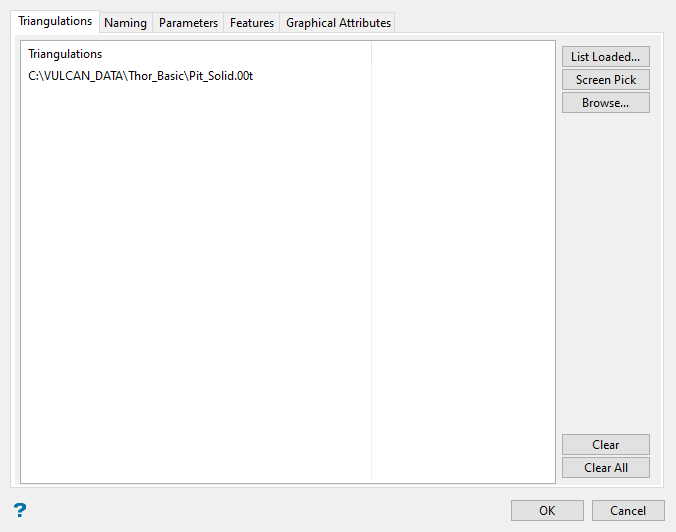
Click one of the buttons on the right side of the panel to populate the triangulations list. All the triangulations on this list will be the ones cut into shells.
-
List Loaded - Populates the list with the names of all the currently loaded triangulations.
-
Screen Pick - Allows you to populate the list with the triangulations you select from among those loaded already loaded into Vulcan.
-
Browse - Allows you to populate the list be selecting triangulations from an Explorer window.
TipTo remove a triangulation from the list, highlight the triangulation name and press the Clear button.
To remove a group of triangulations from the list, use the left mouse button in combination with the SHIFT key to highlight the adjacent triangulations, or use the CTRL key to highlight non-adjacent triangulations, then click Clear.
To remove all of the triangulations, select the Clear All button.
-
-
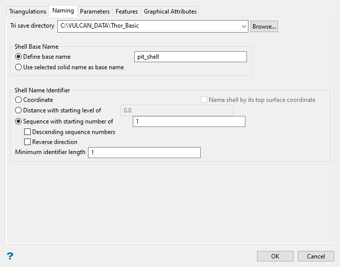
Click the Naming tab at the top of the panel.
-
Select the directory that will be used to store the resulting triangulations in the field labelled Tri save directory. By default, this field will automatically show your current working directory.
Click the Browse button if you want to store the triangulations in a different location or within a subdirectory.
 Browse button
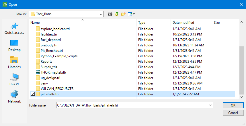
Figure 1 : Clicking Browse allows you to store the resulting shells in another location or to create a new subdirectory.
Use the
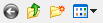 icons to go to the last folder visited, go up one level, create a new folder, or change the way details are viewed in the window.
Once you have located the desired storage folder, click on the folder name before clicking OK.
When creating a new directory, remember to add the (.tri) extension to the folder name.
Example:
New_Directory.tri -
Select either Define base name or Use selected solid name as base name to provide a name for the new triangulations. The base name can contain up to 40 alphanumeric characters (no spaces allowed).
-
Select a naming method using one of the three Shell Name Identifier options.
-
Coordinate - This is rounded up to the next whole number. We recommend that you use the coordinate value as the shell identifier when working with orthogonal planes as this will result in a more concise name.
Important: Do not use the coordinate value when working with non-orthogonal planes because the coordinate references could be inaccurate.
-
Distance - You will be required to enter a starting level when using distance.
-
Sequence number - This method appends a number onto the name of each new triangulation. You will need to provide a starting number for the sequence.
NoteSelect Descending sequence numbers to reverse the naming direction.
Select Reverse direction to produce sequence numbers in the opposite direction.
The resulting triangulations will be named using the following naming convention:
Example:
<base_name>_<shell_identifier>.00t -
-
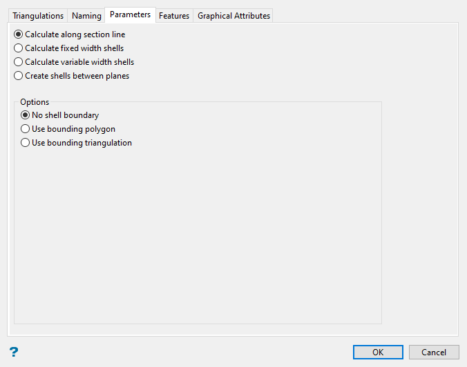
Click the Parameters tab at the top of the panel.
-
Select how the triangulation will be cut into shells.
Note: This pane will display different options depending on which method you select to create the shells.
Calculate along section line
Select this option to create shell triangulations along a nominated section line.
NoteThe section line, which is selected once the panel has been completed, will affect the orientation and width of the resulting shells.
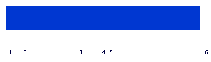
Figure 2 : Original Triangulation and Section Line.
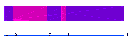
Figure 3 : If the section line has no W tag, a new shell is created at each point in the line and the width of the shells is the distance between points.
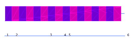
Figure 4 : If the section line has a W tag, then the shells are created perpendicular to the section line and the width of the shells is equal to the W tag.
You can limit the boundaries of the shell by selecting one of the following options:
-
No shell boundary - No boundary limits will be applied.
-
Use bounding polygon - Boundaries will be established by the polygon you select.
-
Use bounding triangulation - Boundaries will be established by the triangulation you select.
Calculate fixed width shells
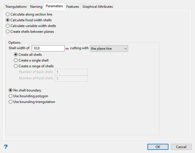
Select this option to generate shell triangulations with fixed widths.
-
Enter the width of the resulting shells in the field labelled Shell width of.
-
Select the desired cutting plan from the drop-down field labelled cutting with. Use the plane line if you have an existing polyline. Use a digitised line to draw the line on the screen dynamically.
You have the option to create all the shells, create a single shell, or create a range of shells. If you choose to create a range of shells, you will need to enter the number of shells to create both in front of and behind the line that you select.
You can limit the boundaries of the shell by selecting one of the following options:
-
No shell boundary - No boundary limits will be applied.
-
Use bounding polygon - Boundaries will be established by the polygon you select.
-
Use bounding triangulation - Boundaries will be established by the triangulation you select.
Calculate variable width shells
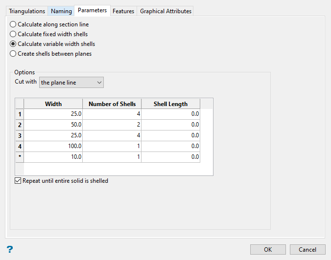
Select this option to generate shell triangulations with varying widths.
-
Enter the Shell width. You can enter as many different widths as you need.
-
Enter the number of shells to create with each width.
-
Enter the desired Shell length for the shell slice. This will be the length of the solid, measured from the centre of the triangulation outward, that will be shelled.
Note: A shell length of zero [ 0 ] will be processed as infinity, meaning the full length of the triangulation or triangulations will be shelled.
-
Select whether or not you want this pattern to repeat until the entire solid is shelled.
Note: A plane that is generated from the Select section by line and Select by points options will now always generate a plane whose normal vector points to the right of the point sequence.
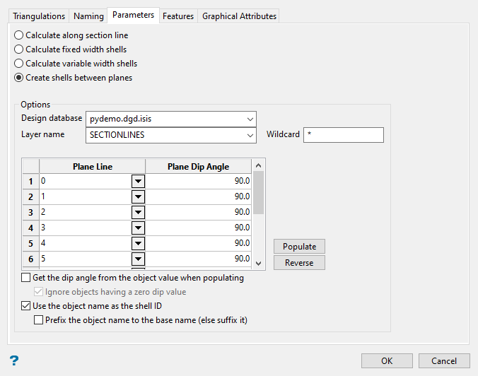
Create shells between planes
-
Select this option to generate shell triangulations that use a series of different polylines that are stored in a single layer.
-
Select the design database and layer name that contains your lines.
-
Select the lines you want to use from the layer. A list of all available objects will be shown in the Plane Lines drop-down list.
-
Enter the angle you want the shell to dip in the column labelled Plane Dip Angle. The dip is the angle of the section from horizontal. Valid dip angles are between -90° and 90°.
-
Select Get the dip angle from the object when populating if you want to read the dip angle from the object value field. The dip can be assign to the object value of a line by using Design > Attribute Edit > Value.
-
Selecting Ignore objects having a zero-dip value will prevent a shell from being created if there is no dip value.
-
Select Use object name as shell ID to append the object name to the base name of the shell triangulation.
Note: When using this option, if you do not select the option Prefix the object name to the base name, the object name will be added as a suffix instead.
-
Click the Populate button to automatically fill the table with all the values found in the drop-down list.
Click the Reverse button to reverse the order of the list.
Note: The individual lines are recognised by the object name assigned to them. You can assign a name to each object in a layer by using the option Design > Attribute Edit > Name.
-
-
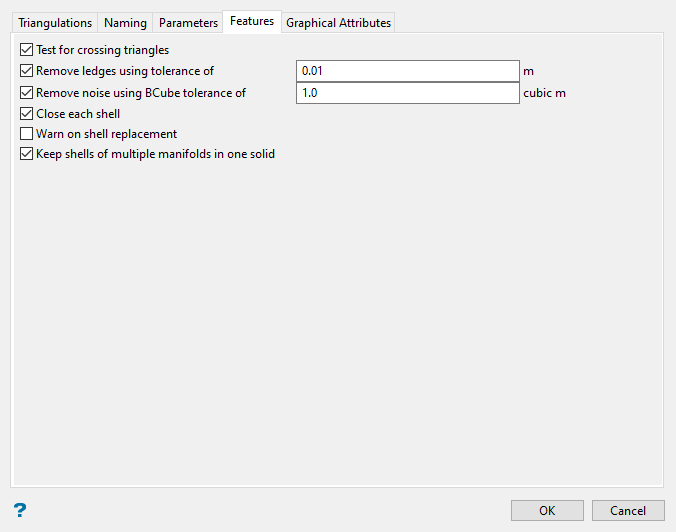
Click the Features tab at the top of the panel.
-
Select Test for crossing triangles to test before creating the new triangulations.
-
Select Remove ledges using angle tolerance to remove the ledges that may be formed where the resulting triangulation contains triangles that are parallel to the clipping plane. When this occurs, crossing triangles are formed when trying to close the triangulation. Triangles that deviate from the clipping plane by less than (or equal to) the entered angle tolerance will be deleted.
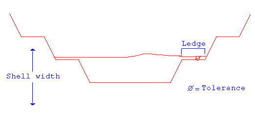
Figure 5 : Remove Ledges
-
Select Remove noise using BCube tolerance to remove the little disconnected sections of a triangulation that are created when performing the clipping. It is possible to get a lot of little sections and one main section of interest. The BCube tolerance refers to the volume of the cube that bounds the island in 3D space.
Example:
(MaxX - MinX) * (MaxY - MinY) * (MaxZ - MinZ)The islands are formed when a clipping plane passes just below a peak.
-
Select Close each shell to add triangles to the new triangulations.
-
Select Warn on shell replacement to be warned whenever an existing triangulation is about to be replaced. Enabling this check box will result in a prompt being displayed informing you of the possible replacement.
-
Select Keep shells of multiple manifolds in one solid to combine small separated sections of a shell and treat them as a single solid.
-
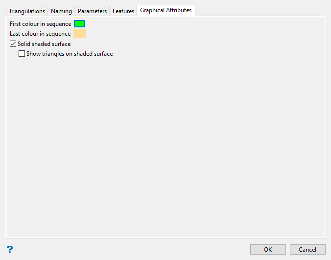
Click the Graphical Attributes tab on the top of the panel.
-
Specify the first and last colours for the shell colour sequence. The shells will be coloured using the sequence of colours on the colour table between the selected colours.
-
Select Solid shaded surface to display the new triangulations as solid shaded surfaces, i.e. not transparent and no mesh lines.
Use the 3D/Solid Shading button
 on the Graphics toolbar to turn the shading on/off once the triangulation has been loaded.
 -
Select Show triangles on shaded surface to display the actual triangulation lines as well as the solid shading.
Note: Solid shading requires additional memory.
-
Click OK.

