Tri Polygons
Create Triangulations from Polygon End Plates
Use this option to take a group of polygons, end plate each polygon individually, and append the result together. This option is often useful for imported data (e.g. DXF) as other packages sometimes represent a solid as a group of polygons. The Tri Polygons option allows you to turn it into a triangulation.
Note: No topological corrections are performed. That is, if the polygons do not meet properly or have trifications, then this will be reflected in the resulting triangulation.
You can use the Split option to split a triangulation that consists of many disjoint sections.
Instructions
On the Model menu, point to Triangle Solid, and then click Tri Polygons.
The Multiple Selection box displays. From this box, choose your method of selecting the polygons and select the polygons. The polygon objects will be shadowed as they are selected.
The following panel is then displayed.
At the top of the panel, specify the folder path and file name of the triangulation.
Follow these steps:
-
Confirm the Triangulation directory of the desired triangulation. The triangulation storage preferences, which are configured in Vulcan Preferences > Paths/Directories, will control the path name displayed in this field by default. You can type a new path into this field to alter the directory, or navigate to a new folder location with the Browse... button in the following step.
-
Enter a new triangulation name or choose an existing one from the Triangulation name drop-down list, which will contain all triangulations found within the Triangulation directory. Use the Browse... button to change the directory location and select a file from another location. Selecting an existing file will require you to confirm that you wish to overwrite the file's original contents. When prompted to confirm overwriting, click Cancel if you want to assign a different file name.
-
Proceed to the tabs in the panel to set the triangulation display options.
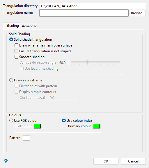
Shading tab
Use this tab to set the triangulation style (wireframe or solid), shading options, and colour and pattern.
Follow these steps:
-
Choose either the Solid shade triangulation or Draw as wireframe option:
The Solid shade triangulation option displays the triangulation as a solid shaded surface; that is, not transparent and no mesh lines. Solid shading requires additional memory. There are several other optional settings under this option:
-
Draw wireframe mesh over surface: Select this checkbox to display a wireframe mesh on the solid surface.
-
Ensure triangulation is not striped: Select this checkbox to avoid strange lighting effects. For the majority of triangulations, it will not be necessary to select this option. However, if a triangulation appears to be striped, then you may want to reload it with this checkbox selected.
Note: Using this option may slow down the loading process.
-
Smooth shading: Select this checkbox to apply smooth shading to your triangulation. Each vertex will be coloured according to the angle the triangulation makes with the light direction. Smooth shading, also known as Gouraud shading, blends these vertex colours over the triangulation.
Note: The rounded appearance of smooth shading is only a graphic attribute and does not affect the volume of the triangulation.
The Surface definition angle refers to the angle required between the triangle normals for the surface to be considered continuous. If the surface definition angle is less than the angle between triangle normals, then the triangles are considered to be on different surfaces.
Example: If the angle between your bench and batter is 70°, then set the surface definition angle less than 70° to ensure that the bench and batter look like different surfaces on the triangulation. If you set this angle to 0°, then all of the triangles are considered to be on different surfaces. If you set the angle to 180°, then all of the triangles are considered to be on one surface, and the colours will blend over the entire triangulation.
When the Use load time shading checkbox is selected, the lighting calculations used to shade the triangulation are performed at load time using the current light direction and a two-sided lighting model. This means that the shading will not change until the triangulation is reloaded, even if the direction of the light is changed later. This lighting technique is used in versions prior to Version 4.0.
NoteOn some graphics cards, this option may be significantly faster than allowing changes in the light direction to change the shading of the triangulation dynamically. However, this is not always the case, particularly on newer cards where this option may in fact make the display slightly slower.
The fact that a two-sided lighting model is used means that this option may be used to correct the display of triangulations that have checker-board effects due to inconsistent ordering of triangle points.
The Draw as wireframe option displays the triangulation as a wireframe. There are several other optional settings under this option:
-
Fill triangles with pattern: Select this checkbox to display the triangulation with pattern-filled triangles.
-
Display simple contours: Select this checkbox to display contours on the model at intervals specified in the Contour interval field.
-
-
Choose either the Use RGB colour or Use colour index option to select a colour for the triangulation. The selected colour is used for the wireframe and as a base colour for the lighting effects. Although both options appear to be similar, the Use RGB colour option provides you with a more extensive colour range to choose from.
-
(Optional) Click the Pattern option to select a pattern from the available list in the dialog. This selection is visible for the wireframe triangulation display option when the Fill triangles with pattern checkbox is selected above.
-
(Optional) Go to the subsequent tab to set advanced triangulation display settings.
Note: Click OK at the bottom of the panel at any time to save and apply the currently selected triangulation display options, or click Cancel to close the panel without saving changes.
Advanced tab (Optional)
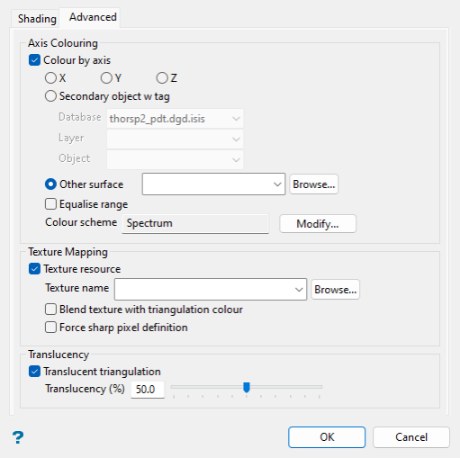
This tab allows you to apply optional features to your triangulation, such as translucency and texture mapping, including the option to drape an image over the triangulation.
Note: The following features are only accessible if the Solid shade triangulation option was selected in the previous section.
Follow these steps:
-
Select the Colour by axis checkbox to colour the triangulation by its X, Y, or Z-axis, by the W tag of a secondary object, or by the Z-axis of another surface (i.e. a triangulation or grid).
-
X, Y, or Z-axis: Select one of these options to colour the triangulation with the selected colour scheme applied to the respective axis extents of the triangulation.
-
Secondary object w tag: Select this option to choose from the Database, Layer, and Object drop-down lists, which display items from the current working directory. The selected colour scheme will be applied to the respective object’s W tag extents to colour the triangulation at coincident points.
NoteThe X, Y, and Z-axis values of the subject triangulation vertices and the object points must match for the object’s W tag value to colour the triangulation at each point. If there are unmatched points, a pop-up dialog will appear stating how many vertices weren't coloured.
-
Other surface: Select this option to choose another surface (triangulation or grid) file in the current working directory from the drop-down list, or click Browse... to select a file from a different location. The selected colour scheme will be applied to the other surface’s Z-axis extents to colour the triangulation at projected points.
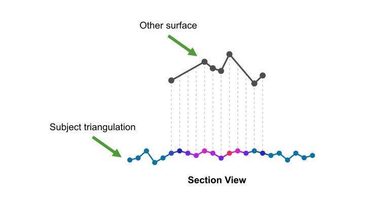
NoteWith this option, points from the other surface will be projected (in plan-view orientation) onto the subject triangulation and the other surface’s Z-axis values will be used to colour the triangulation at corresponding vertices. If portions of the subject triangulation fall outside of the extents of the projected other surface, then the minimum Z-axis value of the projected other surface will be used to colour the triangulation in these areas.
Since colours are only applied to points projected to each vertex of the triangulation, a loss in colour detail may result when the other surface is less detailed spatially than the subject triangulation.
See the graphic below for a depiction of how the Z-axis values of another surface are used to colour the subject triangulation (the subject triangulation’s colour spectrum is set to blue for lowest values and red for highest values).
Select the Equalise range checkbox to equalise the colour distribution. If this checkbox is selected, then the colouring values will be converted from absolute to percentile. As a result, the colour ranges are increased where values are close together.
Note: Equalising the colour distribution will also allow you to create colour schemes to display specific percentile values, e.g. top 10% as red and bottom 10% as blue.
The Colour scheme field is set to Spectrum by default. Click Modify... to open the Select Colour Scheme panel with the following options:
-
Colour by spectrum: Select this option to colour the triangulation by spectrum. Select the desired spectrum type from the drop-down list. The colour spectrum is applied to the axis values used to colour the triangulation, with the smallest values represented by the colour on the far left of the selected spectrum and the largest values by the far right.
If you select the Between two RGB values option, you will need to nominate two colours to stretch over the triangulation axis values. For example, if you select red and blue, then the small values would be red, the middle values purple, and the large values blue. The colour of the middle values is an average of the two chosen colours.
-
By Vulcan colour scheme: Select this option to colour the triangulation by using a Vulcan colour scheme. A default scheme file and type will be entered automatically, which can be altered. Select the Scheme file, Scheme type, and Colour legend from the drop-down lists. Colour schemes can be edited using the options in Analyse > Legend Editor, or by right-clicking on the appropriate scheme file (
.scd) in the Specifications folder of the Vulcan Explorer and selecting Open with Legend Editor from the context menu.
-
-
Select the Texture resource checkbox to drape an image file or, alternatively, the image contained within an image registration file (
.ireg) over the triangulation. The available drop-down list will contain all texture files found within your current working directory. Use the Browse... button to select a file from another location.NoteYou can use the ECW image format to apply a very large texture to a triangulation. For example, over 1 billion pixels may be interactively viewed using this option.
Draping a previously configured and captured image (contained within the IREG file) can result in a faster approximation of your data. Refer to the Screen Dump options under the Graphics toolbar for more information on capturing images.
Path names for texture files will be stored according to the path name preferences (absolute or relative) set in Vulcan Preferences > Paths/Directories.
Select the Blend texture with triangulation colour checkbox to blend the solid shaded triangulation colour with the image, allowing you to view the lighting and texture effects.
Select the Force sharp pixel definition checkbox to force textures to display with sharp pixel definition.
-
Select the Translucent triangulation checkbox to apply a level of translucency to the triangulation. A translucency value of 50% will be applied by default when this box is checked. When the slider is at the far left end, the triangulation is solid and therefore not translucent; this is the same effect as entering
0in the Translucency (%) field. When the slider is at the far right end, the triangulation is fully translucent (invisible); this is the same effect as entering100in the Translucency (%) field.

