Project String
Use the Project string option to create a projection of a pit/dump outline from a nominated angle to a nominated or relative level, or until it intersects a grid or triangulation model.
Instructions
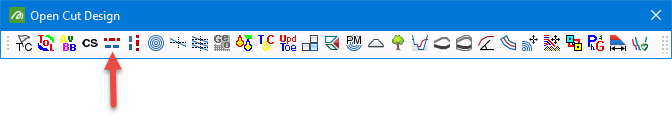
On the Open Pit menu, point to Open Cut Design, then click Project String.
You can also click the Project String button ![]() from the Open Cut Design toolbar.
from the Open Cut Design toolbar.
Follow these steps:
-
Select the pit outline to project. This can be polygon or line. After selection, the panel will be displayed.
-
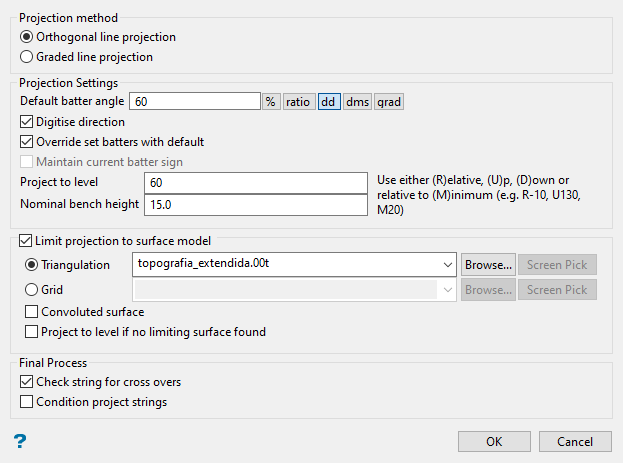
Select the Projection method.
-
Orthogonal line projection treats the line as if flat.
-
Graded line projection accounts for the dip, but only when the batter angle is greater or equal to the line's gradient.
-
-
Enter the Default batter angle. This will be used on faces in the outline that have nothad batter angles assigned (through the Open Pit > Open Cut Design > Assign Berm/Batter Valuesoption).
-
Select Digitise direction if you want to select the direction of projection by clicking on the screen. You will be able to make your selection after you have completed filling out the panel and clicked OK.
After the panel closes, a rubberband will be displayed that is attached to the input polygon or line and your cursor. The rubberband shows the direction of projection. Click anywhere on the screen when you decide on the direction.
Note: If this option is selected, the option Maintain current batter sign will be disabled.
Note: The length of the rubberband or the location you click does not affect the projection other than indicating the direction.
TipThe point sequence of the line or polygon determines the way in which it is projected. A clockwise string projects upward and outward, or downward and inward. A counter-clockwise string projects upward and inward, or downward and outward.
Use a clockwise string for a pit and a counter-clockwise string for a dump.
If you are unsure of the direction of digitising, use theAnalyse > Label > Point Labeloption to display the point sequence, or right-click on the polygon and select Label > Point Sequence from the context menu.
-
Select Override set batters with default to replace all existing batter angles with the default batter angle, i.e. all angles, regardless of whether or not they have been assigned a value, become the default angle. If this checkbox is not selected, the W tag values will be used for projection.
Batter angles used in the projection are retained in the projected string so that they can be used for the next projection.
-
SelectMaintain current batter sign to maintain the sense of an overriding batter. Only the batter angle will be overridden, the direction will be based on the sign of the batter, which is encrypted in the W tag of each line segment.
-
Select Project to a level (optional) to limit the projection.
Enter the level you want to project to. The level can be defined in one of five ways:
Prefix Level Projection Method No prefix Absolute r Relative u Project up to an absolute level d Project down to an absolute level m Project up from the minimum level An absolute value without an alphabetical prefix creates a horizontal bench at that level.
Figure 1 below illustrates how prefixing the level with the letter 'r' creates a bench at a height relative to the Z values of the outline. The bench can be projected downwards by entering a negative value.
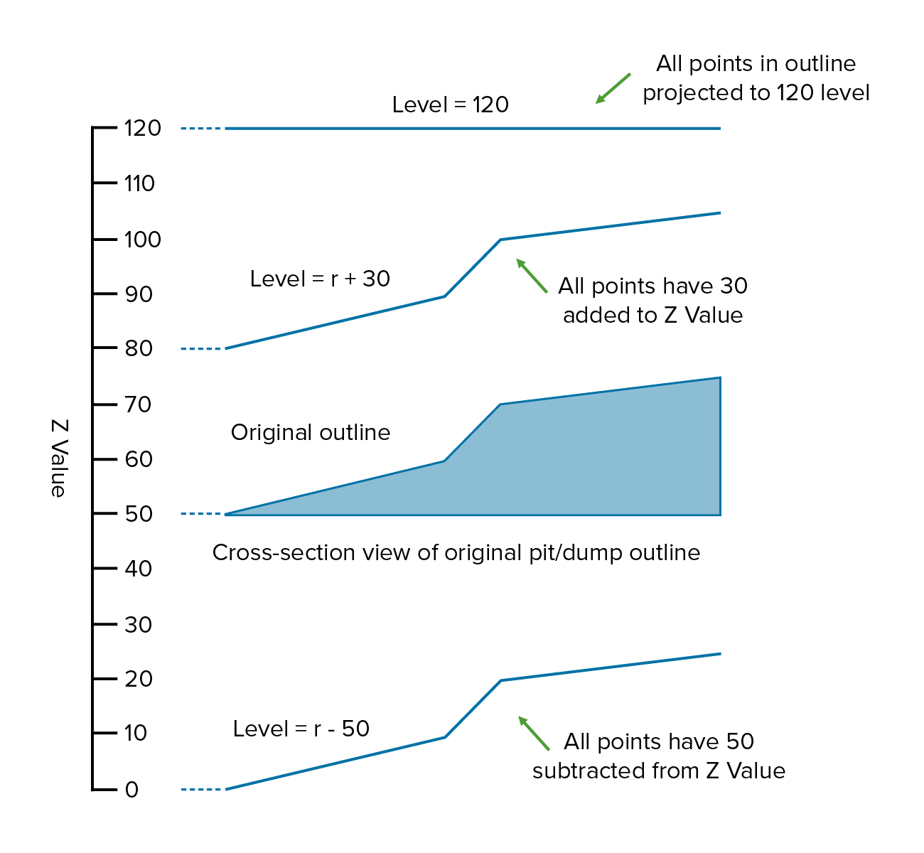
Figure 1 : Projection Method (Absolute/Relative)
Figure 2 below illustrates how a bench can be created at a known absolute maximum or minimum level using these methods. The 'd' prefix will project any part of the string above the specified Z value down to this Z value. The rest of the outline is left unchanged. The "u" prefix will project any part of the outline that is below the specified Z value up to this Z value. Again the rest of the outline is left unchanged.
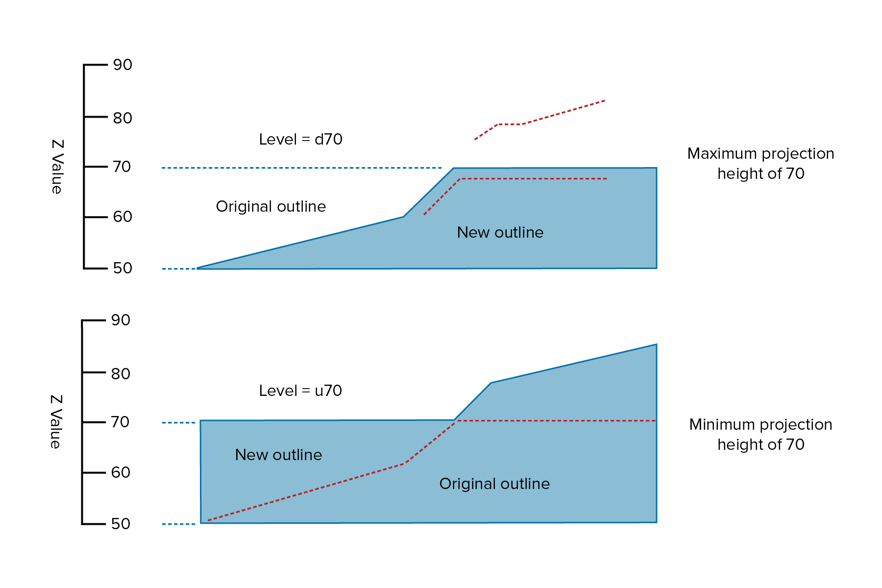
Figure 2 : Projection Method (Up/Down and Absolute Level)
Figure 3 below illustrates how to project a bench to a minimum level using a relative value when the absolute level is unknown. Projecting from a minimum level is useful for generating dumps where the initial toe string is lying on the topography and you want to create level benches.
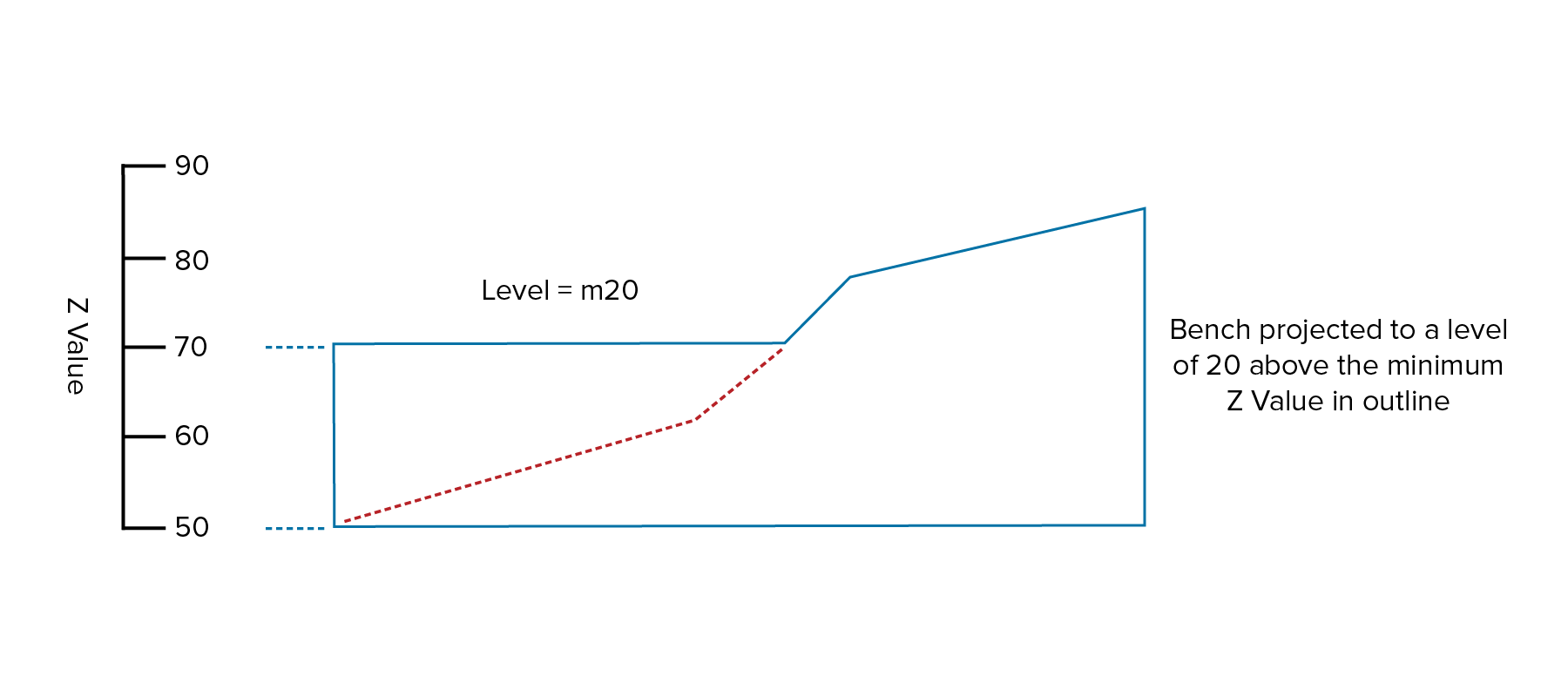
Figure 3 : Projection Method (Up from a Minimum Level)
-
Enter the Nominal bench height. This value is used to increment the value in the Project to Level field once the panel has been completed. This way when the panel is redisplayed, the numeric value in the Project to Level field is ready for the projection of the next bench.
-
Select Limit projection to surface model to limit the projection to an existing (not necessarily loaded) triangulation or grid. Only one or the other can be chosen, but not both.
-
Triangulation - Select this option to use a triangulation as the limiting surface. The list contains all triangulations in the current working directory. Click Browse to select a file from another location.
-
Grid - Select this option to use a grid as the limiting surface. Click Browse to select a file from another location.
-
-
Select Convoluted Surface if the surface is convoluted through the plane of projection. This is usually true at low projection angles. A more complex algorithm to resolve ambiguities that may be present in the convoluted surface is used for the projection.
Note: The projection will take considerable longer with this option enabled.
If the string you want to project lies partly underneath and partly above the surface, and you want to project the entire string to the surface, then you must also select the Project to Level option. Select a value that is greater than the highest value at which the line will intersect the triangulation.
-
Select Project to level when no limiting surface found if you are projecting to a grid, or triangulation surface, but part of the projection does not intersect with that surface. The part of the bench that does not intersect the surface will be projected to the level specified in the Project to Level field. If the check box is not selected, then this part of the bench will have the same Z values as the original outline.
Note: You must specify a grid or triangulation surface for outlines with zero batter angles (the default batter angle is set to 0.0°).
-
Select Check string for cross overs to remove these crossovers. Projections cause an object to shrink or grow. As a result, crossovers may occur.
-
Select Condition projected strings to perform checks on the nominated toe or crest strings to determine if points must be added or deleted to satisfy specified conditions. Refer to the Open Pit > Open Cut Design > Condition String option for more information.
-
Click OK. The projected outline displays as a highlighted string. Choose whether to retain or reject the projection. If you reject the string, you are returned to the Project String panel, allowing you to change the panel setup and re-project if desired.
Select another outline to project. Right-click to exit the option.

