Constraints
Use this section to specify the design constraints that the automatic ramp must honour in order to be accepted as a valid design. The layer in which to store the ramp as well as the maximum time allotted for processing are also defined through this section of the interface. For more information, see the Automatic Ramp Overview .
Instructions
The Automatic Ramp option uses a tree interface. Select branches from the tree menu on the left as described in the instructions below:
On the Underground menu, point to Development, and click Automatic Ramp, then select Constraints from the tree menu to display the Constraints panel.
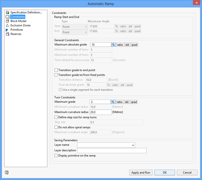
Ramp Start and End
Use this section to define the way the start and end locations are defined. There are two types available for each location; 'Point' and 'Segment'. If 'Segment' is specified, then a maximum angle between the segment and the direction of the ramp can be defined.
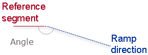
Start/End
Select 'Point' or 'Segment' from the drop-down lists. We recommend that you select 'Segment'' if you have existing reference start/end ramps or developments. The 'Point' entry provides no control on the initial or end orientation of the ramp.
Maximum Angle
Enter the horizontal angle. This field is only applicable when using the 'Segment' entry.
The horizontal angle can be entered as a percentage, a ratio, in decimal degrees or in gradian units. To do so, select the appropriate angle format button and enter the value. The format of <negative value>:<value> must be used when entering negative ratios, for example '-1:7'.
For example : To enter a grade value of 50%, select the % button and enter '50'. Select a different angle format button to convert a value.
General Constraints
This section to specify the design constraints that the Automatic Ramp option must honour in order to be accepted as a valid design.
Maximum absolute grade
Enter the maximum grade (positive or negative) for the ramp. Automatic ramps will have a grade that is less than this maximum. Vulcan will automatically add more turns if needed in order to meet this constraint.
Minimum number of turns
Enter the minimum number of turns that can be added to the ramp.
Maximum number of turns
Enter the maximum number of turns that can be added to the ramp.
Note: When spiral ramps are allowed, one turn can be more than 360°. In order for a turn to be considered as a separate turn it must be separated by straight segments.
Time allotted for processing
Enter the maximum amount time that Vulcan will use to create different feasible ramps.
Transition grade to end point
Select this check box to allow smoother connection with flat development. If this check box is selected, then the ramp will decrease the absolute grade so it connects at a lower grade at the end point. This check box will be selected for both the start and end of the ramp.
Transition distance
Enter the distance that will be used to reduce the grade from the general ramp to the grade at the final connection (at the end of the design).
Final absolute grade
Enter the grade at the end of the ramp. The grade can be entered as a percentage, a ratio, in decimal degrees or in gradian units. To do so, select the appropriate angle format button and enter the value. The format of <negative value>:<value> must be used when entering negative ratios, for example '-1.7'.
Turn Constraints
This section to define constraints for turns and spirals.
Minimum/Maximum curvature radius
Enter the limits for the turn radius.
Maximum grade
Enter the maximum. Unlike straight segments, the grade in curves can be set to a different value.
The grade can be entered as a percentage, a ratio, in decim al degrees or in gradian units. To do so, select the appropriate angle format button and enter the value. The format of<negative value>:<value > must be used when entering negative ratios, for example '-1.7'.
Define step size for ramp turns
Select this check box to control the number of points in a turn. If this check box is selected, then a step size can be defined. This value refers to the distance between consecutive points in a turn. If this check box is not checked, then one point per degree will be used instead.
Do not allow spiral ramps
Select this check box to avoid spiral ramps. If this check box is checked, then a maximum curvature angle can be defined. The curvature angle will be used to limit the spiral ramps.
Saving Parameters
This section to specify the layer that will be used to store the resulting ramp.
Layer
Enter the name of the layer that will be used to store the resulting ramp. The drop-down list contains the names of all layers found in your currently open design database.
To create a new layer, enter the layer name. The layer name:
-
- may contain up to 40 characters.
- must begin with an alphanumeric character [0-9] or [a-z].
- cannot include spaces.
- can include hyphens [ - ], plus signs [ + ], underscores [ _ ], periods/dots [. ].
- can include the special characters of ÁÂÃÀÇÉÊÍÓÔÕÚÜÑ that are used in the Spanish and Portuguese languages.
Description
Enter a description to further describe the contents of this layer. The description can be up to 80 alphanumeric characters and may include spaces. If a description is not entered, then a default description will be used instead. If the chosen layer already has an assigned description, the description displays when the layer is selected. Existing layer descriptions can be overwritten.
Related topics
Tutorial

