Primitives
Use Primitives to specify a primitive that will be used in order to evaluate a goal or reserves. Predefined or custom primitives can be used. For more information, see the Automatic Ramp Overview .
Instructions
The Automatic Ramp option uses a tree interface. Select branches from the tree menu on the left as described in the instructions below:
On the Underground menu, point to Development, and click Automatic Ramp, then select Primitives from the tree menu to display the Primitives panel.
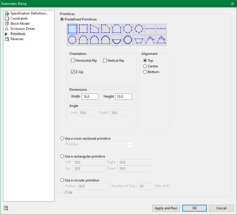
Primitives
Use this section allows to select primitives to be used with the ramp centreline. By using primitives the line can be converted to a volume that can be evaluated. The volume will be used for reserves as well as to evaluate the criteria when using a block model variable.
Located at the top of this section is a collection of predefined geometric shapes. To use a shape as a primitive, select the appropriate image.
Figure 1 : Predefined Shapes
Orientation
Horizontal flip : Select this check box to swap left and right sides of the shape, mirroring them horizontally along the vertical line passing through the origin.
Vertical flip : Select this check box to swap top and bottom of the shape, mirroring them vertically along the horizontal line passing through the origin.
Z-up : If a line is spread along the XY plane, the dominant direction becomes visibly inclined off the vertical axis. For such curves, the only possible solution is to forcefully define dominant direction as Z-axis. This option does that job and also provides additional control over dominant direction for frequently used cases of primitive application.
For backward compatibility, Z-up is enabled by default. For users who want to use primitives with vertical segments in their lines need to disable this option explicitly.
Note: If Z-up is applied to a line that has vertical segments, twisting of the shape is possible near the vertical segment. Usually the drive type lines don't have vertical segments but if one needs to attach a vertical shaft to a drive, it is advised to use another line without Z-up attribute.
Dimensions and angle
Use this section to specify the height and width of the chosen primitive.
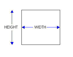
Figure 2 : Dimensions
In the case of the primitives located on the far right of the second row, you can also specify the left and right angles.
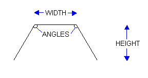
Figure 3 : Angles
Alignment
Use this section to indicate the alignment line. This refers to the position where the primitive will be applied. The position (when viewed through the Editor tab) will be marked with a red dot.
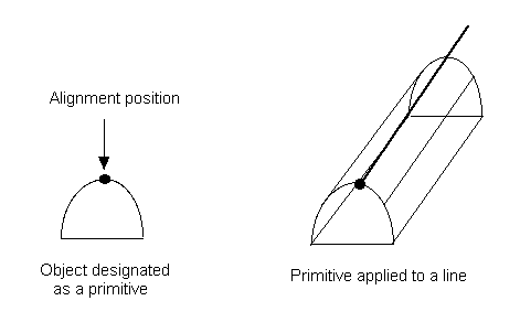
Figure 4 : Top Alignment
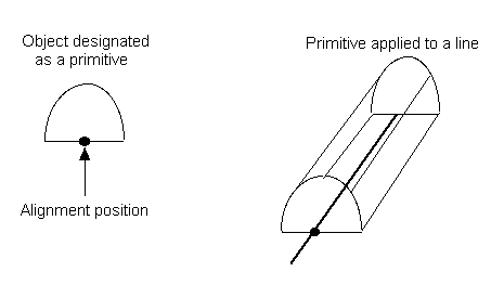
Figure 5 : Bottom Alignment
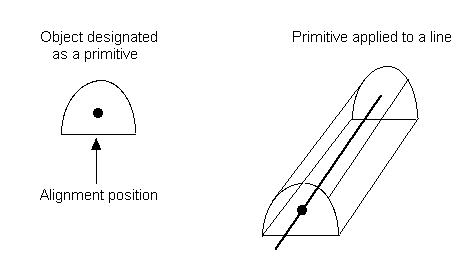
Figure 6 : Create Alignment
Use a cross sectional primitive
Select this option to use an existing primitive. You will need to select the primitive from the drop-down list. The drop-down list contains all primitives defined in your Primitives specification file (.pgd).
Use a rectangular primitive
Select this option to use a rectangular primitive. You will need to specify the size of the rectangle. The string will be placed in the centre of the rectangle.
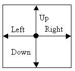
Figure 7 : Cross section of rectangle
Use a circular primitive
Select this option to use a circular primitive. You will need to specify the radius, as well as the number of steps (a maximum of 63). The string will be placed in the centre of the radius. The number of steps refers to the number of points that will be created on the circle.
Related topics
Tutorial

