Fault Solid Creator
This tool simplifies the creation of fault solids by providing users with an interface that can create fault block solid triangulations from a given base solid. Base solid is basically a solid covering the area of interest that will be split into fault block solids.
The input data consists of fault surface and fault lines. The fault lines are provided as design polylines that may be supplied in multiple design layers. The dip of the line on per-point basis may be encoded in the name of the point. Otherwise the interface gives user an ability to supply a default dip. Dip is defined in the same way as in Throw Faulting for Integrated Stratigraphic Modelling.
Workflow
The key elements of the workflow around Fault Solid Creator are:
- selection of the base solid
- selection of the solid triangulation that will be split into the fault blocks
- select the way the information about cutting surfaces is presented
- select the lines defining cutting surfaces
- select user-defined cutting surfaces
- edit intermediary results
- preview the results
- execute the process
Instructions
On the Grid Calc menu, point to Integrated Stratigraphic Modelling, and then click Fault Solid Creator to display the following panel.
The panel is split mainly into 6 tabs:
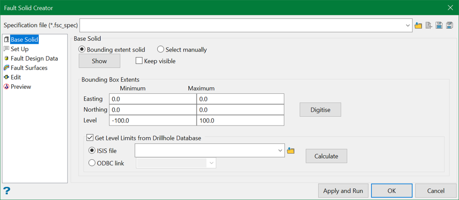
This section allows users to define the base solid.
This section allows users to define line settings and miscellaneous output settings.
This section allows users to select the design lines representing the fault lines.
This section allows users to use custom surface triangulations when the cutting surface cannot be produced by a projection of line.
This section allows merging of the solid blocks that are produced by sectioning of the base solid by all selected surfaces.
This section allows users to visualise components that ultimately define the splitting of the base solid.
Specification
Specification is a pre-saved file that contains the selections for the panel elements. The Fault Solid Creator specification files have extension .fsc_spec.
Specification file
Use the drop-down list to select the specification file if it is in the current working directory, or browse for it in another location by clicking the Browse button. A new file may also be created by typing the name of the new file in the textbox and clicking the New button.
-
 Browse
 -
 New
New -
 Save
Save -
 Save as
Apply and Run
This button executes the splitting process and saves the design settings to the specification file currently displayed in the specification file combo box.
OK
This button only saves the settings to the specification file for future use.
Related topics

