Set Up
This section allows defining miscellaneous settings required for creating the fault blocks.
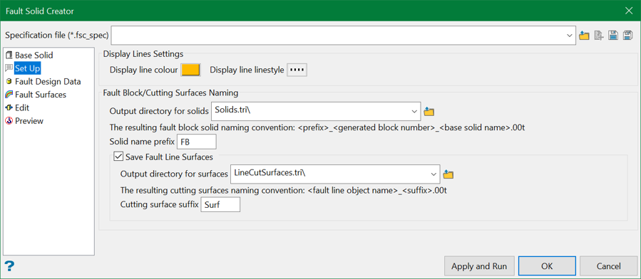
Display Line Settings
This refers to the display of already selected design fault lines during the preview as well as manual pick of the design fault polylines in the Fault Design Data. In the latter case, it helps to identify which lines were already selected for future creation of cutting surfaces. The colour also defines the colour of the cutting surfaces in the Preview section.
Fault Block/Cutting Surfaces Naming
This section defines simple rules for storing output files. Because the tool is highly interactive, users may choose to save the results of each run in separate directories. Choose a directory from the drop-down list or browse from another location.
The Solid name prefix option defines the prefix for the output block names. The naming convention for the output fault block solid is:
<prefix>_<generated block number>_<base solid name>.00t
If the base solid is box, the base name is Box and the output fault block solid will be named FB_0_Box.00t
Save Fault Line Surfaces
Users may choose to save fault line surfaces projected from the design fault lines. Choose the output directory for saving the output surfaces from the down-drop list or browse from another location.
The Cutting surface suffix option define the suffix for the output surfaces. The naming convention for the output fault line surface is:
<fault line object name>_<suffix>.00t
Note: The base names are extracted from object names. Make sure all objects have unique names or else some surfaces can be overwritten.
Related topics

