Base Solid
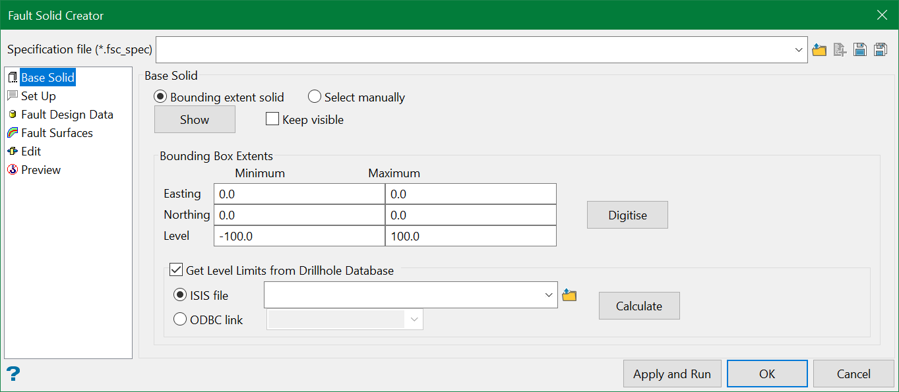
In order to create a set of fault blocks, one needs to start with a solid covering the area of interest, which is called the Base Solid. This section allows users to define a base solid.
Base Solid
There are two ways in which the base solid can be defined.
Bounding box extent
This option allows selecting bounding box extent as the base solid. Users can manually enter the coordinates and levels for the bounding box extent or choose from the screen using the Digitise button.
Show
This button minimises the panel and displays the base solid on the screen.
Keep Visible
This option keeps displaying the base solid on the screen even after the preview panel is closed.
Get Level limits from Drillhole Database
Select this option to extract levels from a drillhole database. Select the desired database and use the Calculate button to autofill the level limits from that database.
Select manually
Alternatively, users can also manually select an existing solid using this option. This can be useful when users want to subdivide an already split solid.
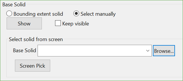
Choose a base solid from the drop-down list or browse from another location. Optionally, users can also manually pick the solid from the screen.
Related topics

