Fault Design Data
This section allows users to select the design lines representing the fault lines. Those lines will be projected up and down outside the base solid to produce the boundaries of the fault blocks.
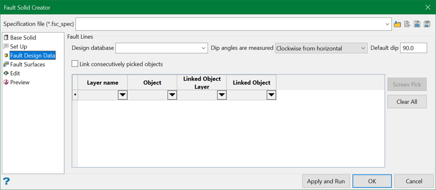
Fault Lines
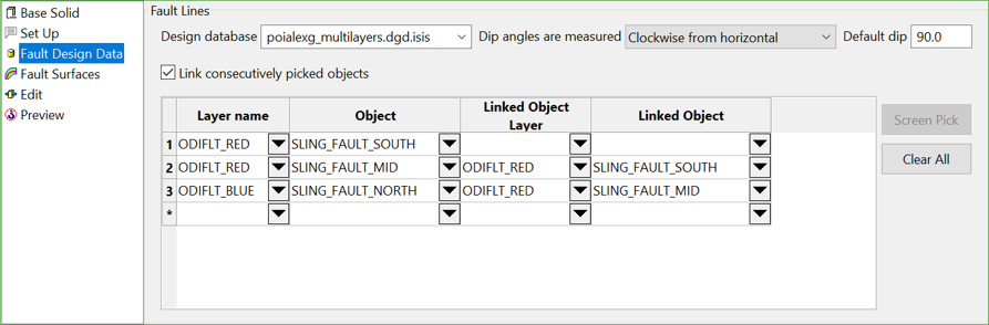
Select a design database from the drop-down list that contains the required fault lines. Choose the direction on how dip angles are measured. Similar to Throw Faulting in Integrated Stratigraphic Modelling, the dip angles can be encoded into the names of the individual points on the line. For points that do not have the angle encoded in their names, the default value is used.
It is possible to choose the data components from each drop-down list in the table grid. However, the best approach is to pick the lines from the screen.
Link consecutively picked objects
This option allows considering consecutive lines as part of one fault line. It defines the way the lines are extended outside the base solid.
As an example, let's take reference of the following configuration:
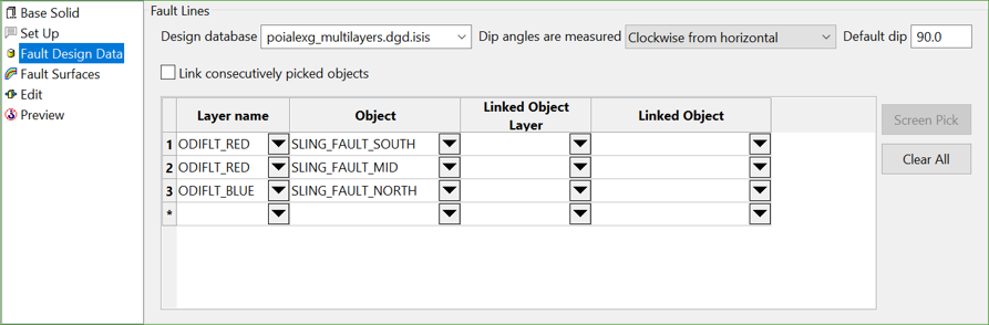
The three lines with their point sequences are shown below.
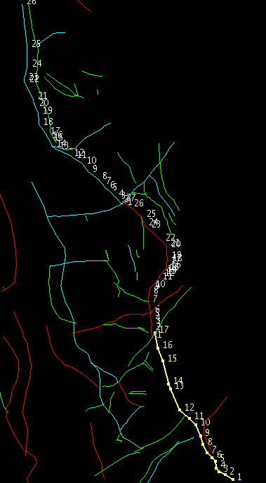
Figure 1: Three selected lines with their point sequences
Without linking the consecutively picked objects, the projection will be as follows.
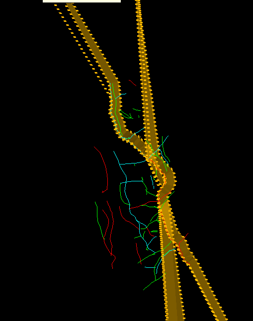
Figure 2: Result without linking the consecutively picked objects
After linking the consecutively picked objects, the same lines produce a single surface that cuts the base solid, as shown below.
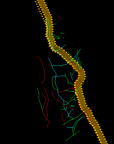
Figure 3: Result after linking the consecutively picked objects
And the configuration appears something like this.
Important: However, there is a limitation in the projection capabilities. If the dip value for the line points is more than 90 degrees, the line has to be split into two parts: one with dip value smaller than 90 degrees and the other with higher than 90 degrees. Otherwise, the projection will not produce the expected result.
Related topics

