

Hole
Source file: hole.htm
The Hole group on the Home tab contains tools that allow you to view hole attributes and properties, as well as create hole patterns and intervals.

Hole Tabular View
Use the  Hole Tabular View to view a specific set of hole attributes depending on the preset you select. The tool also allows you to export this data as a PDF or CSV file.
To enter the Hole Tabular View panel, follow these steps:
-
Select the required holes in the view window.
-
On the Home tab, in the Hole group, select
Hole Tabular View.
The Hole Tabular View panel will appear. The panel contains two column fields and one table that allow you to customise and view the required hole attributes.Tip
After selecting the required holes, you can also enter the Hole Tabular View panel the following ways:
-
Using the keyboard shortcut Ctrl+T.
-
Right-clicking in the view window and selecting
Hole Tabular View from the context menu.
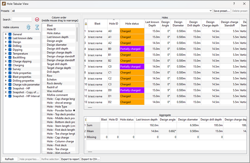
-
Viewing hole data
To view hole data using the hole tabular view, follow these steps:
-
Select a set of holes in the view window.
-
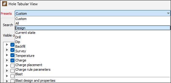
Enter the Hole Tabular View panel and select the required preset from the Presets drop-down.
Note: A preset is a specific set and order of columns that is displayed in the Hole table.
-
Optionally, edit the displayed attributes by completing the following steps:
-
In the Visible columns field, click the
 button corresponding to the required category to view all of the attributes the category contains.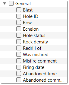
Tip: Use the
 button to expand all categories at once. To close this detailed attribute view of all categories, click the
  button.
Note: Any snapshots of the selected blast are also listed as categories and contain the related snapshot hole attributes.
-
In the Visible columns field, select the checkboxes of the attributes you wish to view, or clear the checkboxes of the attributes you wish to hide.
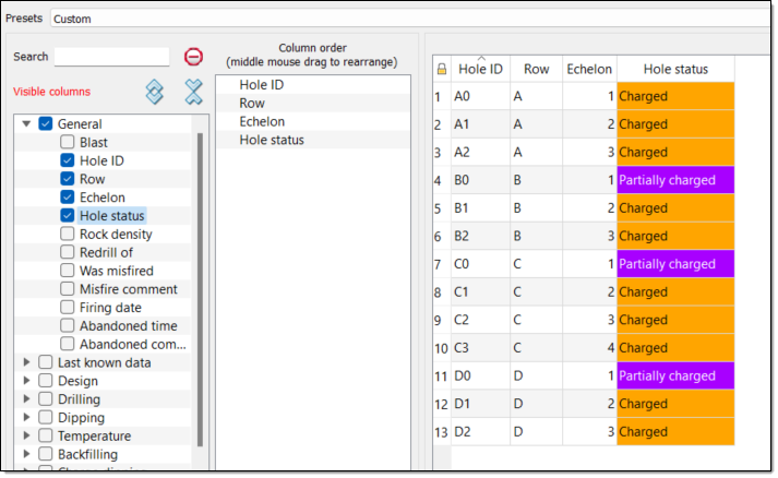 Note
NoteYou can also specify the hole attributes you wish to view in either of the following ways:
-
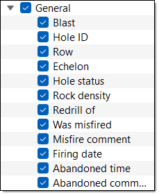
Select the category checkbox to add every attribute in that category to the Columns order field and Holes table. You can also clear any checkboxes corresponding to the attributes you do not wish to view.
-
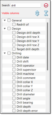
Enter an attribute or category name into the Search field. BlastLogic will present the results that match the search in the Visible columns field. Select the checkboxes of the results you wish to view or clear the checkboxes of the results you wish to hide.
-
-
Optionally, reorder the attributes in the Column order field by dragging the attributes to the required locations using the middle mouse button.
TipRight-click on an attribute in the Column order to view the following context menu options:
-
Select column. Select to view the attribute column in the Holes table.
-
 Remove column. Select to remove the attribute from the Holes table.
-
-
You can interact with the Hole Tabular View panel as follows:
To highlight a hole in the view window, select the row corresponding to that hole in the Holes table.
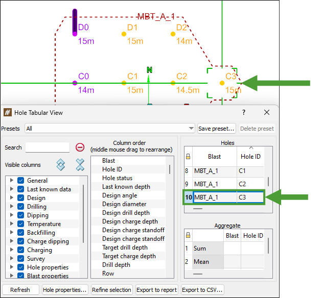
To view the properties of a certain hole, select that hole in the Holes table and click Hole properties....
To view the hole attributes of a different blast, select the required blast in the project explorer. The information on holes from the selected blast will appear in the panel.
To further refine the selection of holes, select the required holes in the panel with Ctrl+click or Shift+click, then click Refine selection. BlastLogic will reduce the number of rows to the selection made.
To export the data as a PDF file, click Export to report.
To export the data as a CSV file, click Export to CSV....
Creating a custom preset
Custom presets allow you to save the columns present in the Hole table and the order they appear in. To create a custom preset, follow these steps:
-
Select a set of holes in the view window.
-
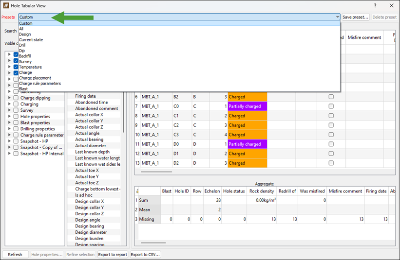
Enter the Hole Tabular View panel, go to the Presets drop-down and select Custom.
-
Edit the appearance and order of the columns in the Holes table.
 Expand for more information on editing the appearance and order of the columns.
To edit the columns in the Hole table and the order they appear in, follow these steps:
-
In the Visible columns field, click the
button corresponding to the required category to view all of the attributes the category contains.Tip: Use the
button to expand all categories at once. To close this detailed attribute view of all categories, click the button.Note: Any snapshots of the selected blast are also listed as categories and contain the related snapshot hole attributes.
-
In the Visible columns field, select the checkboxes of the attributes you wish to view. BlastLogic will add the selected attributes to the Column order field and Holes table, in the order that you selected the attributes .
NoteYou can also specify the hole attributes you wish to view in either of the following ways:
-
Select the category checkbox to add every attribute in that category to the Columns order field and Holes table. You can also clear any checkboxes of the attributes you do not wish to view.
-
Enter an attribute or category name into the Search field. BlastLogic will present the results that match the search in the Visible columns field. Select the checkboxes of the results you wish to view.
-
-
Add any other attributes to the Column order field and Holes table by selecting the checkboxes of the required categories and attributes.
-
Optionally, reorder the attributes in the Column order field by dragging the attributes to the required locations using the middle mouse button.
TipRight-click on an attribute in the Column order column to view the following context menu options:
-
Select column. Select to view the attribute column in the Holes table.
-
Remove column. Select to remove the attribute from the Holes table.
-
-
-
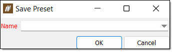
Click Save preset.... The Save Preset panel will appear.
-
Enter a preset name using the Name field or drop-down menu.
-
Click OK. The preset will now appear in the Preset drop-down.
Note: To delete a preset you no longer need, select it from the Presets drop-down and click Delete preset.
Create Pattern
Use the  Create Pattern tool to define a grouping of holes, known as a pattern.
To create a pattern, follow these steps:
-
Click on a blast in the project explorer or select the blast in the view window.
-
On the Home tab, in Hole group, select
Create Pattern. The Create Pattern panel will appear. By default, BlastLogic fills the Name field with the name of the selected blast.
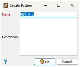
Note: Optionally, enter a different name into the Name field and enter a description into the Description field.
-
Select the holes in the view window that you wish to include in the pattern. BlastLogic will include them in the view window within an area named New boundary.
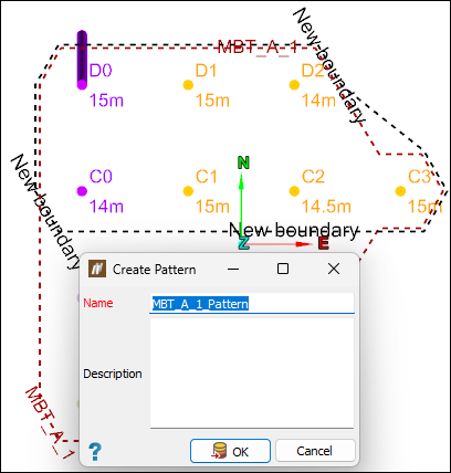
-
Click OK. BlastLogic will save the pattern to the
 Patterns container located in the parent blast container in the project explorer.
Note: To edit a pattern, see the steps in the Edit section of the Pattern on the Context Sensitive Ribbons page.
Edit Intervals
allows you to define labelled regions along a hole, known as intervals. Defining an interval requires specifying both an upper and a lower surface. Use the  Edit Intervals tool to add or modify intervals in the hole. To open this tool, select the required holes in the view window and go to the Home tab > Hole group > Edit Intervals. The Edit Intervals panel will appear.
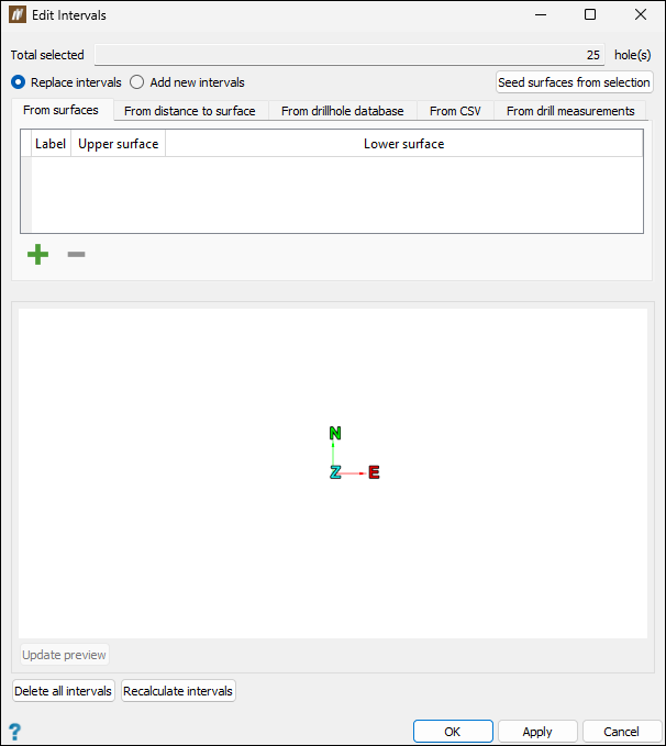
You can add hole intervals based on the following sources:
-
From surfaces
Expand for instructions
To add hole intervals to a hole using surfaces, follow these steps:
-
Ensure the From surfaces tab is open.
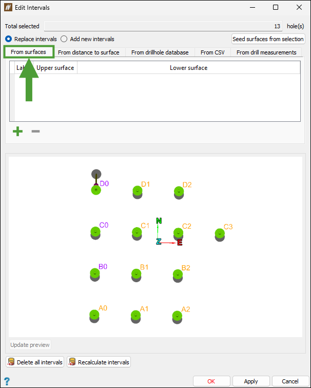
-
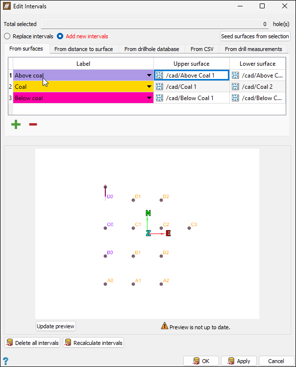
Click
 to add a label. Repeat this until the required number of labels appears in the table.
 -
Select an interval label. By default, BlastLogic sets the interval label to the first interval that is listed in Interval labels (Home tab > Setup group >
 Site). You can change the interval by clicking on the label cell drop-down and selecting the required interval label. See Interval labels for details.
 -
Specify the upper and lower surfaces. You can specify these surfaces in the following ways:
-
Select the cell you wish to assign a surface to and enter the surface location. For example, surfaces are typically found in the
cadcontainer with the location/cad/<surface name>. -
Drag the surface from the
cadcontainer in the project explorer or from the view window, into the required cell, using the middle mouse button.
Note: Only one surface is required. If you only select one surface, BlastLogic will create an unbounded interval for the second surface. To create a surface, see the appropriate procedure in Surfaces.
Note:
If you are in the Replace intervals mode and click OK without specifying any surfaces, the specified interval label of all intervals will be cleared. A dialog window will appear for you to confirm this operation.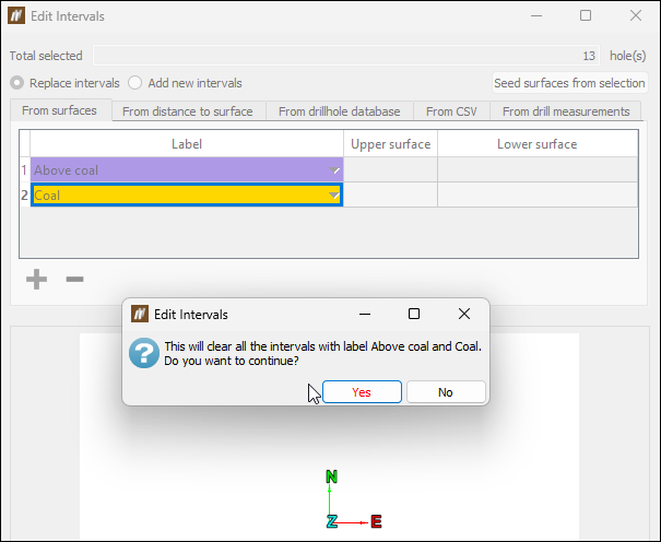
Tip: You can add or remove intervals by clicking
or  respectively.
 -
-
Select the appropriate hole interval update method. You can select either Replace intervals or Add new intervals.
-
Click Update Preview to view the hole intervals.
-
Click OK or Apply.
-
-
From distance to surface
Expand for instructions
Intervals can be defined by the regions of a hole within a specified distance from a surface. Such intervals can help identify the sections of holes that are too close to a highwall or to provide offsets from coal seams. These intervals can then be used in charge rules to avoid charging in these regions.
Follow these steps to add hole intervals from distance to surface:
-
Select holes in the view.
-
Select the holes in your view and go to the Home tab > Hole group and select
Edit Intervals. -
Select the From distance to surface tab.
-
Select either the Replace intervals or Add new intervals radio button and click
 to add a surface.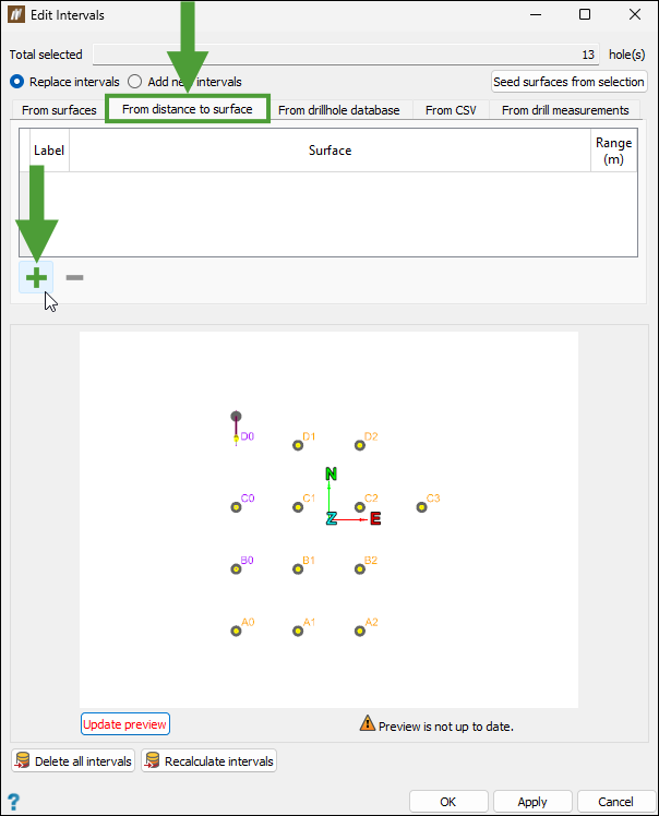
-
Specify the Label by selecting the required option from the drop-down menu.
-
Drag the surface from the
cadcontainer in the project explorer, into the Surface field in the Edit Intervals window, using the middle mouse button. -
Define the Range.
-
Repeat the above steps to add more intervals and click OK or Apply to confirm.
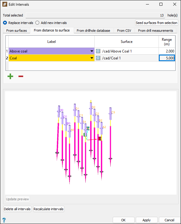
Important: When a surface has been attached to holes (for example, when the holes are applied to an interval), it is published and can no longer be edited.
-
-
From drillhole database
Expand for instructions
To add hole intervals using the drillhole database tab, follow these steps:
-
Go to the From drillhole database tab in the Edit Intervals panel.
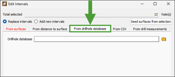
-
Select either the Replace intervals or Add new intervals radio button.
-
Click
 to open the file explorer.
 -
Navigate to the required drillhole database object file (
.dhobj) and click Open.Tip: You can create a drillhole object file by exporting a blast with drill measurements into Maptek GeologyCore. Use the Create Intervals from Downhole tool to add intervals in GeologyCore. The object must then be exported as a drillhole object file such that it can then be imported into BlastLogic. For more information on this process, see Maptek GeologyCore help documentation.
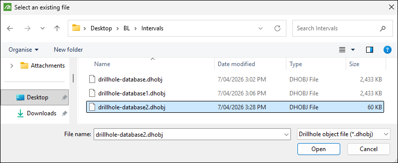
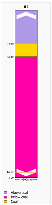
BlastLogic displays a preview of the blast with the updated hole intervals.
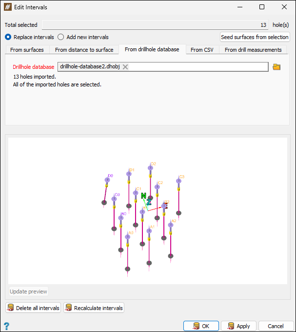
-
Click OK or Apply to confirm the changes.
Tip: You can view the intervals by selecting the Hole Properties tool in the Hole group, and navigating to Decks and Intervals > Intervals.
-
-
From CSV
Expand for instructions
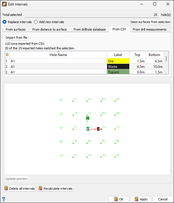
Importing intervals from a comma-separated values (CSV) file allows you to integrate interval information originating from other software packages or derived from post‑processed drill‑measurement data.
To add hole intervals from a CSV file, follow these steps:
-
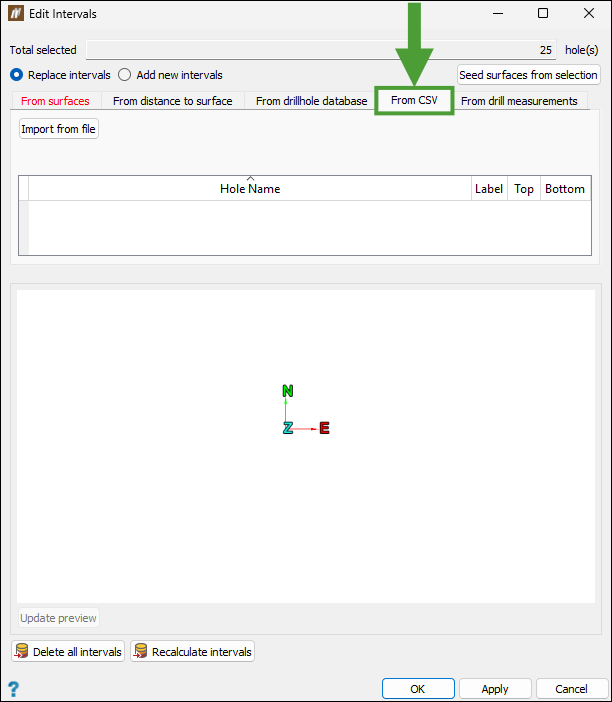
Go to the From CSV tab in the Edit Intervals panel.
-
Select either the Replace intervals or Add new intervals radio button.
-
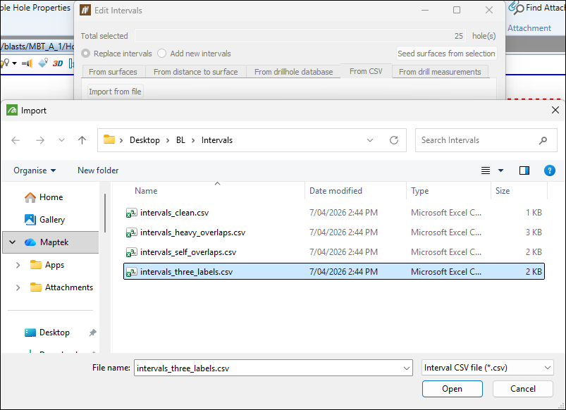
Click the Import from file button, select the required file on your machine, then click Open.
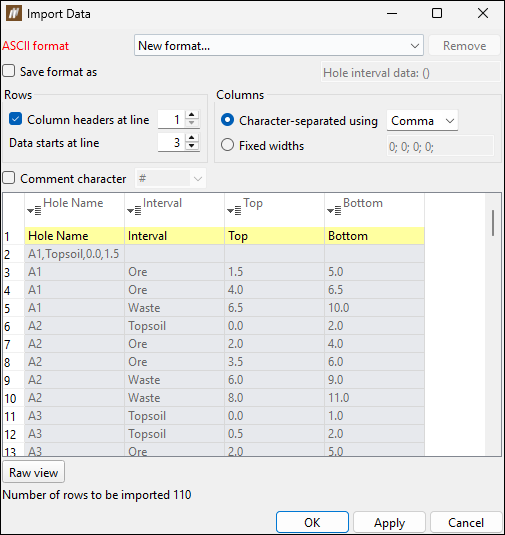
The Import Data panel with the data preview will appear.
-
Follow the steps in the Importing a CSV file procedure.
Note: Compared to the above-linked procedure, the panel for importing intervals does not contain the Import data as drop-down.
-
Click OK or Apply.
will populate the Edit Intervals panel based on the imported data and match the interval label name to interval defined in the Home ribbon > Setup group >
Site (see Interval labels for more details). Note: If BlastLogic cannot identify an interval, a table to map the missing labels will appear.
Note: If you selected the Add new intervals radio button, BlastLogic will merge the data from the file with the existing interval data.
-
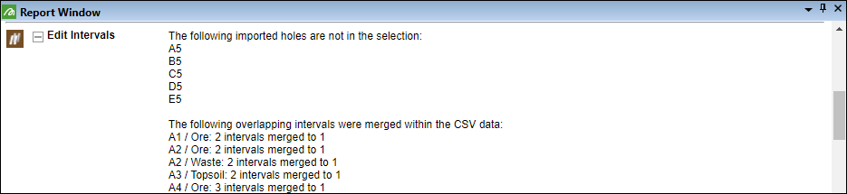
Click OK or Apply to save the interval changes.
will list the information on the holes that were included in the file but not in the selected blast hole range and the information on the merged intervals in the Report Window.
-
-
From drill measurements
Expand for instructions
Use the From drill measurements tab to convert drill measurement (measure-while-drilling) data into intervals using configurable mapping rules. This allows you to classify regions of a hole based on drill measurement properties (e.g. rock type, penetration rate) without needing to export and re-import data through a comma-separated values file.
To add hole intervals from drill measurement data, follow these steps:
-
Go to the From drill measurements tab in the Edit Intervals panel.
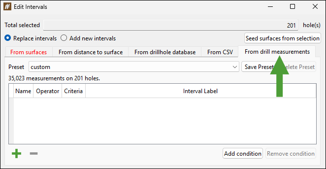
-
Select either the Replace intervals or Add new intervals radio button.
-
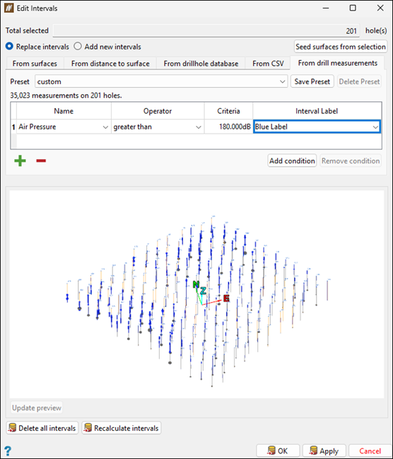
Populate the table. Each row in the table represents a set of conditions. All conditions within a row must be true for the interval label to be applied. In other words, BlastLogic evaluates the selected Operator and Criteria against the chosen Name (drill measurement), and if they are satisfied, the specified Interval Label will be assigned.
Note: Adding a new row creates a separate set of conditions for defining an interval label.
You can populate the table the following ways:
-
Add and configure rows in the table.
Proceed as follows:
-
Click
to add a row to the table. 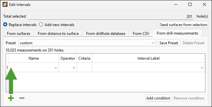
-
Add the target interval labels by selecting the required properties from the drop-downs in the Name, Operator, Criteria, and Interval Label columns.
Click Update preview for the preview window to reflect the created labels.
-
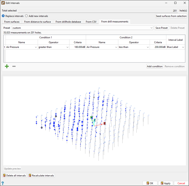
Optionally, add conditions to the defined target interval labels to define precise ranges. Adding a condition to a row means you are introducing an additional requirement that must also be true for that same interval label to apply.
Proceed as follows:
-
Click the Add condition button.
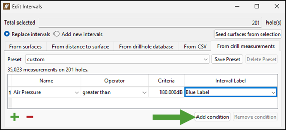
This will add condition columns to the table.
-
Select the required properties from the drop-downs in the Name, Operator, Criteria, and Interval Label columns.
Click Update preview for the preview window to reflect the created labels.
-
Add as many rows and conditions to the table as needed to define your interval criteria.
-
To remove a condition from the table, select a cell corresponding to that condition and click the Remove condition button.
Tip: Save the defined interval labels for future use by clicking the Save Preset button.
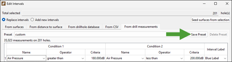
Enter the name for the preset and click OK.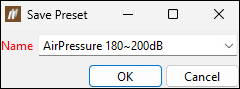
Use the defined presets next time you configure the required intervals. For more information about the presets, see the subpoint below. -
-
-
-
Select the required interval mapping preset from the Presets drop-down.
The drop-down contains the list of created presets that are stored on the BlastLogic Server. The drop-down list defaults to custom which is not a saved preset, but allows you to save your interval mapping configuration. For more information on saving presets, see the Tip above.

-
To remove a preset from the Server, select it from the drop-down and click Delete Preset.

-
-
-
Click OK or Apply to save the interval changes.
-
After adding hole intervals, you can click the relevant buttons to run the following commands:
Delete all intervals: Clear all of the existing intervals on the selected holes.
Recalculate intervals: Update the intervals if changes have been made to the holes or surfaces.
Tip:
Set the view mode to display intervals by going to the View context sensitive ribbon tab and selecting  Intervals or selecting Intervals from the
  Visualisation drop-down on the toolbar.
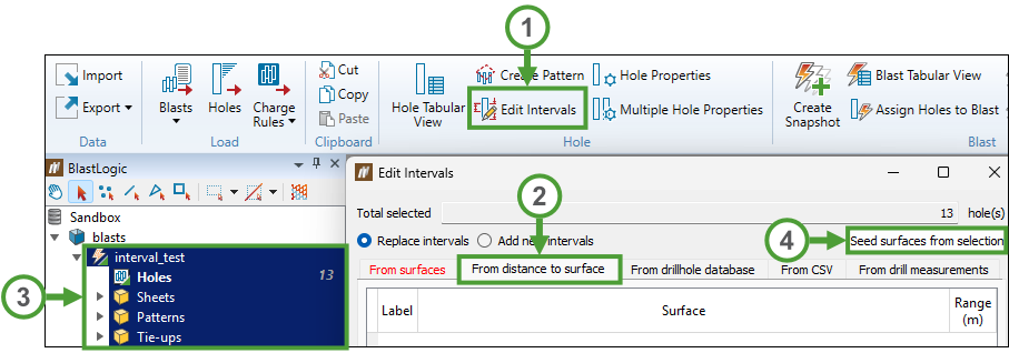
You can reopen the intervals created for a given blast as follows:
-
Go to the Home tab > Hole group and select
Edit Intervals. -
Go to the required tab (From distance to surface in the example below).
-
Select a blast or holes in the project explorer or in the view window.
-
Click Seed surfaces from selection.
The created intervals will be loaded to the Edit Intervals panel.
Hole Properties
Use the  Hole Properties tool to view and edit the properties of a single hole.
To view the properties of a hole, follow these steps:
-
Select the required hole in the view window.
-
On the Home tab, in the Hole group, select
Hole Properties. Tip
You can also enter the Hole Properties panel the following ways:
-
Selecting the required hole and using the keyboard shortcut Ctrl+H.
-
Right-clicking on the hole in the view window and selecting
Properties of <hole name>... from the context menu.
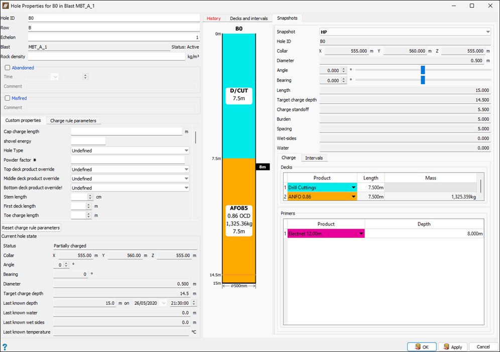
The Hole Properties panel will appear. This panel has the following sections:
-
The left-hand side of the panel displays the current information about the hole, including the custom properties and charge rule parameters that have been specified for it.
-
The right-hand side of the panel shows the history of the hole, the information on the decks and intervals, and any snapshots that were created for that hole. For details, see the Viewing hole history, Decks and intervals, and Snapshots below.
-
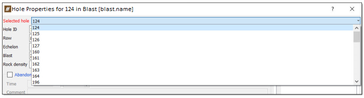
Selecting from multiple holes
You can select multiple holes in the view window, enter the Hole Properties panel and switch between the selected holes using the Selected hole drop-down menu.
Note: This drop-down menu will only appear when you select multiple holes.
See also: Multiple Hole Properties
Viewing hole history
Click on a row in the history table to display the details of that entry.
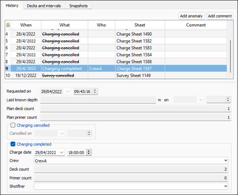
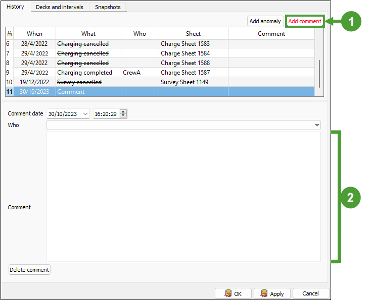
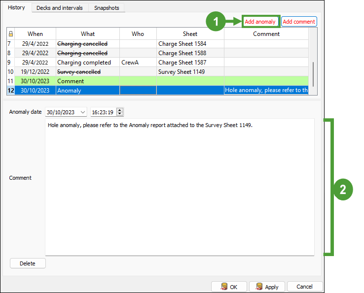
You can also leave a comment or report an anomaly in the records of each hole. To do so, click Add comment or Add anomaly at the top of the hole history table and enter the required information.
| Adding a comment | Adding an anomaly |
|
|
Note: To delete a comment or anomaly entry that is no longer required, select it in the table and click Delete comment or Delete, respectively.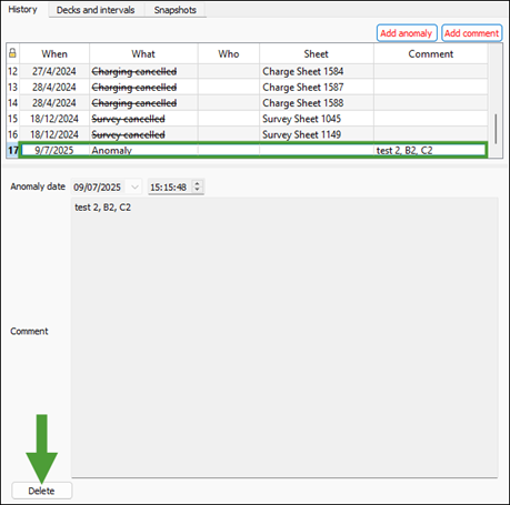
The reported hole anomaly will also be noted in your Blast Summary Report under the Anomalies tab.
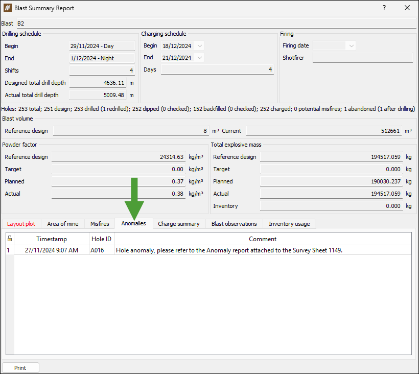
See Blast Summary Report for more information.
Decks and intervals
The Decks and intervals tab contains the following subtabs:
Target charge plan
A target charge plan is the charge plan for the target charge depth, based on the known properties of that hole at the time explosive loading begins. It is intended to represent the ideal loading of a hole given the known conditions at the time of loading.
The Target charge plan subtab is populated when you make changes to the hole's charge plan, either manually or by applying a charge rule. If the charge plan uses a charge rule, the target charge plan is calculated using the same rule applied to the hole at the target charge depth. If the charge plan is manual, the target charge plan truncates (if hole is too long) or extends the bottom charge deck (if hole is too short) to match the target charge depth. The subtab displays the resulting charge decks and primers generated from the applied rule, assuming the hole length is treated as the charge depth for the calculation. BlastLogic displays the hole charge decks and primers in the embedded view window.
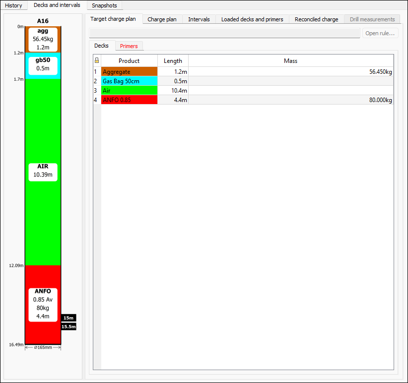
Note: This subtab is read-only. To make any changes to the hole design or charge rule, go to the Charge plan subtab. The target charge plan will be updated automatically to reflect any changes made to the charge plan.
Charge plan
A charge plan is the configuration of explosives and other blast products with which a hole is planned to be charged. The charge plan is the basis from which operators work during blast execution and reconciliation. It can be created manually or automatically by applying a charge rule to the hole.
In the Charge plan subtab, you can open the associated rule to view or edit it. The associated charge rule may be reapplied to update the table if you make any changes to the design of the hole or charge rule. BlastLogic displays the hole charge decks and primers in the embedded view window next to the table.
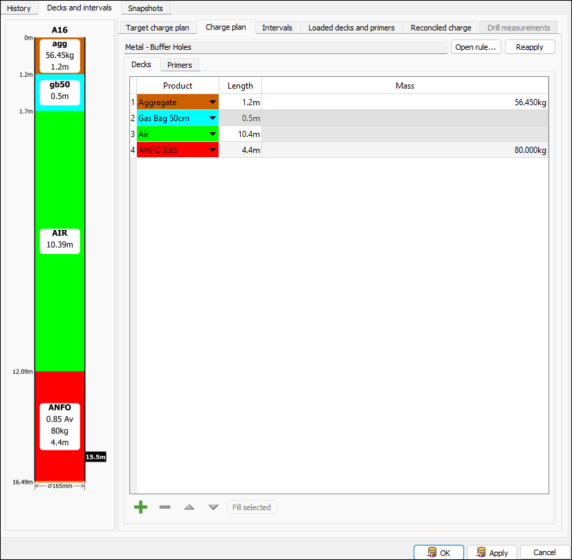
You can edit the products of the charge plan as follows:
Note: Editing the charge plan will remove its association with the charge rule used to calculate it, if one was applied. Editing the charge plan for the hole that is already scheduled for charging on a charge sheet is not possible.
-
Open the Decks or Primers tab and navigate to the product that you want to change.
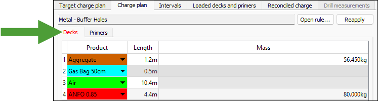
-
Make the required changes as follows:
-
Decks tab
-
To change the product used in the charge rule, double-click on it in the table and select the required product from the drop-down.
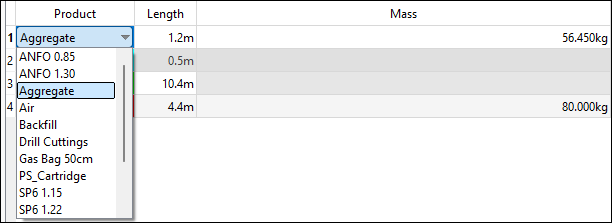
-
To change the length of the deck, double-click the cell in the Length column that corresponds to that product and enter the required value.
-
To change the mass of the product to be used, double-click the cell in the Mass column that corresponds to that product and enter the required value.
-
-
Primers tab
-
To change the product used in the charge plan, click on it in the table and select the required product from the drop-down.
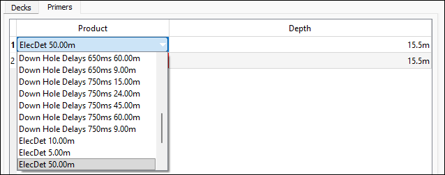
-
To change the depth at which the product should be applied, double-click the cell in the Depth column that corresponds to that product and enter the required value.
-
-
-
After applying the required changes, click OK or Apply to save your changes.
To add a new product to the charge plan, proceed as follows:
-
Navigate to the Decks or Primers tab and click
 at the bottom of the Charge plan subtab.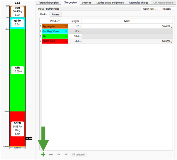
-
Configure the product as follows:
-
Choose the required product type from the drop-down.
-
Set the length and mass (for the deck) or depth (for the primer) for the product.
-
Use the
 and
and  buttons to order the product among other products.
Note: Only deck products can be ordered.
-
-
After applying the required product properties, click OK or Apply to save your changes.
will also include the new product in the embedded view window next to the table.
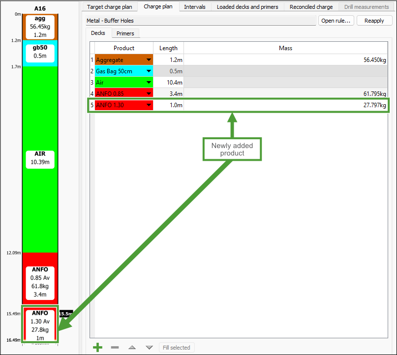
-
Use the Fill selected button to fill the rest of the hole with the selected row's product.
-
Select the product that you no longer require in the list and click
 to remove it from the charge plan.
Note: The , , , , and Fill selected buttons be disabled when a charge sheet has been issued or if there is loaded or reconciled charge data on the hole.
To view or edit the charge rule associated with the selected hole, follow these steps:
-
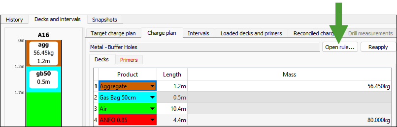
Click the Open rule... button in the Charge plan subtab.
-
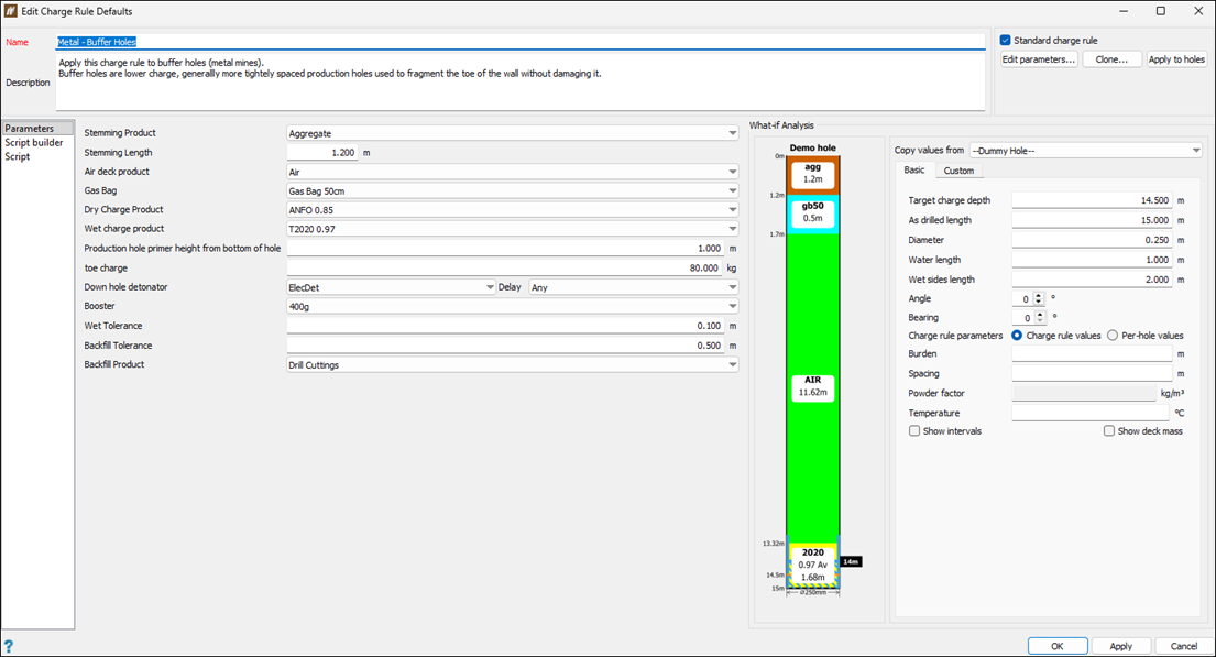
In the Edit Charge Rule Defaults panel, edit the required parameters (see Edit Charge Rule for more information).
-
Click OK or Apply to save your changes.
See also: Create Charge Rule
Intervals
The Intervals subtab shows all the intervals currently defined on the hole.
Note: You can define the intervals for your site in the Interval labels tab of the Site Setup panel (Home tab > Setup group > Site). See Interval labels for more information.
To define an interval for a hole, follow these steps:
-
Select the required interval in the drop-down.
-
Click
at the bottom of the panel. will add the interval to the table.
-
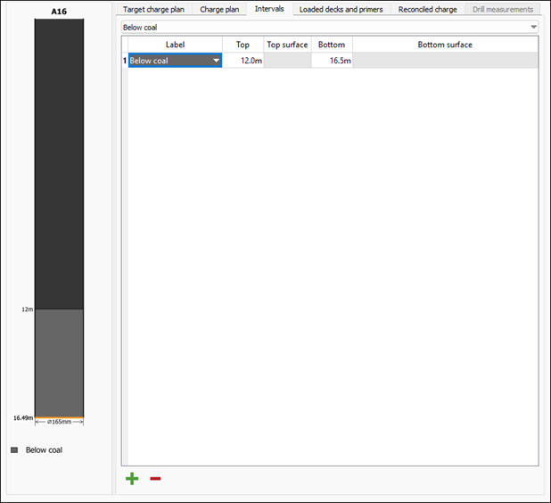
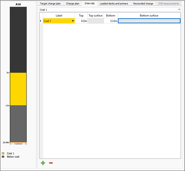
Enter the values in the Top and Bottom columns to specify the top and bottom depths of the interval. will adjust the position of the interval in the embedded hole view next to the table.
-
Repeat the above steps to add more intervals, as required.
 Note
NoteTo view all added intervals in the table, select --All intervals-- from the drop-down.
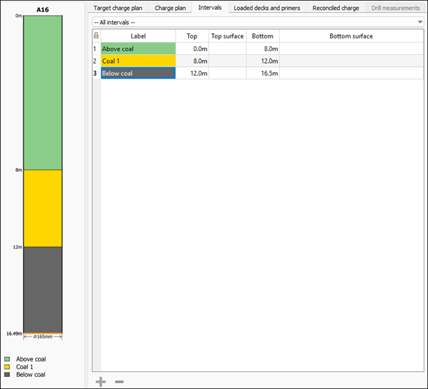
To delete an interval you no longer need, select the corresponding interval from the drop-down, select it in the table, and click
at the bottom of the panel to remove the interval. 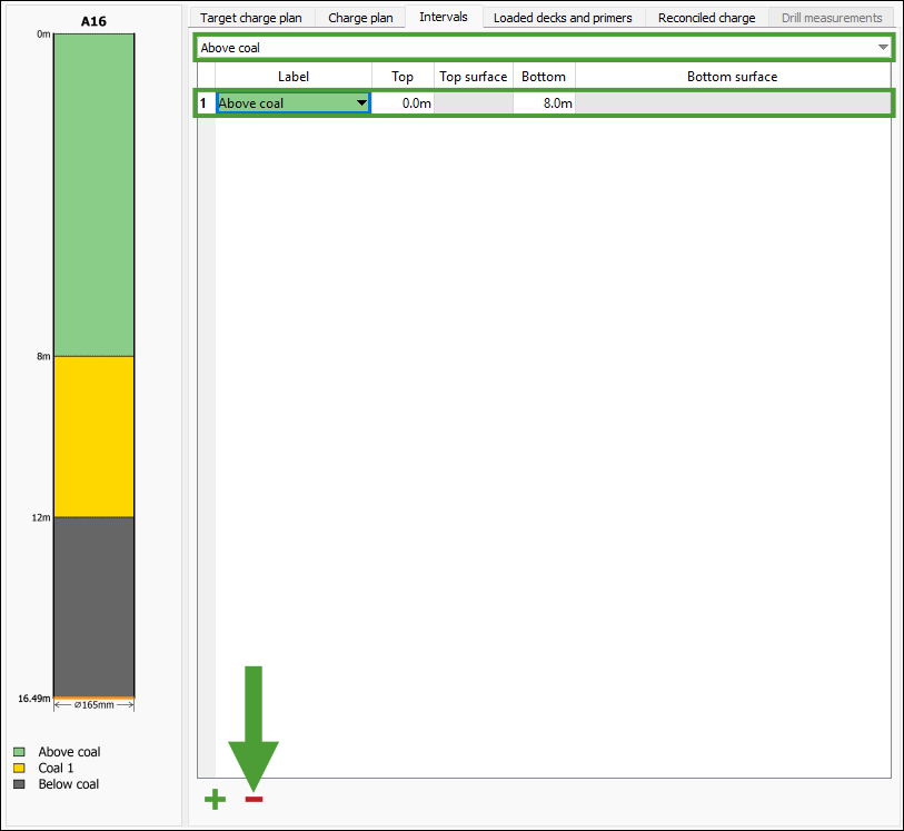
-
After applying the required configuration, click OK or Apply to save your settings.
Loaded decks and primers
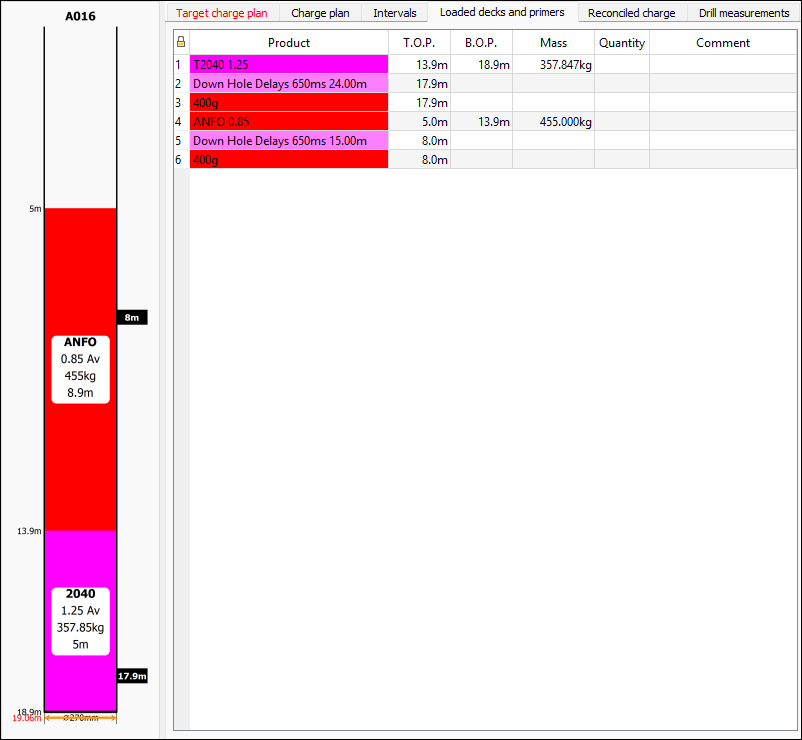
The Loaded decks and primers subtab shows charge data recorded at the time of loading the hole, captured either through the BlastLogic Tablet application or from a drill navigation system configured with the BlastLogic Integration Service. The data displayed here is read-only.
Reconciled charge
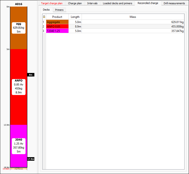
The Reconciled charge subtab shows the reconciled charging decks and primers of the hole in a read-only format.
See also: Charge data reconciliation
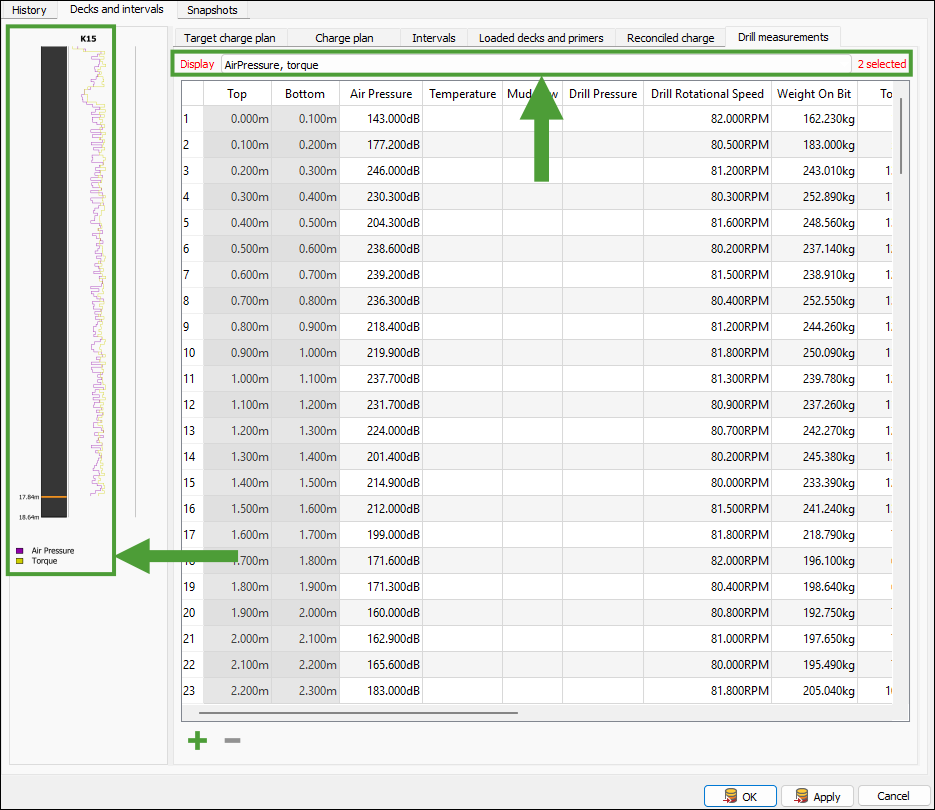
Drill measurements
The Drill measurements subtab displays the drill measurement properties. These measurements are added by the BlastLogic Integration Service, but you can also add them manually the following ways:
-
Via the
 Validate Drilling panel.
 -
By going to the Drilling tab > Drill Measurements group, and selecting
 Import from CSV.
 -
By going to the Home tab > Data group, and selecting
 Import.
For more information, see Validation and Managing Data.
You can set the types of properties in the Drill measurements tab of the Site Setup panel. To open this panel, navigate to the Home tab, and in the Setup group select Site.
See also: Drill measurements in Site Setup panel
Use the Display drop-down to select which properties to visualise. The corresponding values will be shown in the hole side view next to the table.
Snapshots
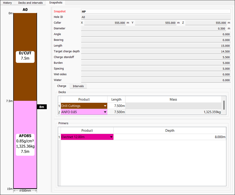
The Snapshots subtab displays the snapshot information of the selected hole. You can select the required snapshot using the Snapshot drop-down. The tab also provides the following subtabs:
-
Charge
The Charge subtab contains the sections Decks and Primers that display tables categorising the deck and primer information respectively for the selected hole.
-
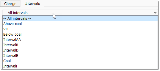
Intervals
The Intervals subtab contains an interval type drop-down and a table. By default, BlastLogic displays all of the intervals, however, you can restrict the table to display only one interval type by choosing it from the drop‑down menu.
Multiple Hole Properties
Use the  Multiple Hole Properties tool to view and edit the properties of multiple holes that you selected, as well as to add comments and record any observed anomalies. The Multiple Hole Properties panel consists of the following tabs:
To enter the Multiple Hole Properties panel, follow these steps:
-
Select the required holes in the view window.
-
On the Home tab, in the Hole group, select
Multiple Hole Properties.
The Multiple Hole Properties panel will appear with the Design tab open by default.Tip
After selecting the required holes, you can also enter the Multiple Hole Properties panel the following ways:Using the keyboard shortcut Ctrl+Shift+H.
Right-clicking in the view window and selecting
Multiple Hole Properties from the context menu.
Design
Use the Design tab to view and edit the main properties of multiple holes. To make changes to the properties of the required holes, follow these steps:
-
Select the required holes in the view window.
-
Enter the Multiple Hole Properties panel.
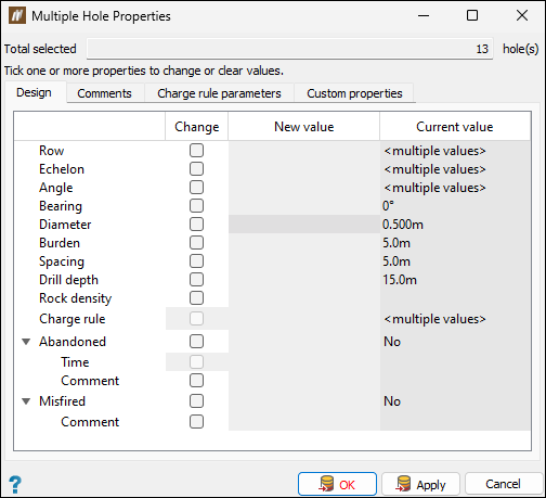
-
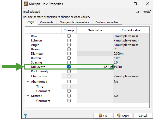
In the Design tab, edit the properties of the holes as follows:
-
To enable editing, in the Change column, select the checkbox corresponding to the property that you want to change.
-
In the New value column, enter the required value.
-
-
After entering the required values, click OK or Apply to save the changed properties for all selected holes.
Comments
Use the Comments tab to leave comments or record anomalies in the records of the selected holes, as follows:
-
Select the required holes in the view window.
-
Click on the Comments tab in the Multiple Hole Properties panel.
-
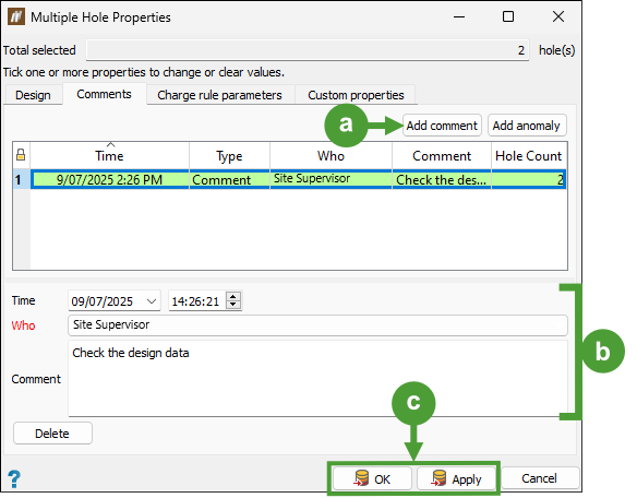
Add the required comment or anomaly as follows:
-
Click Add comment at the top of the table in the Comments tab.
-
Enter the required information (date and time, the person making the comment, and the comment content).
-
Click OK or Apply to add the entry to the holes' history.
-
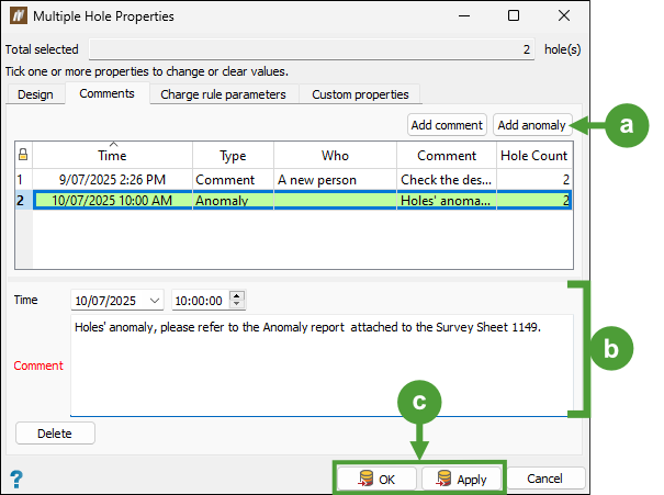
Click Add anomaly at the top of the table in the Comments tab.
-
Enter the required information (date, time, and the anomaly content).
-
Click OK or Apply to add the entry to the holes' history.
| Adding a comment |
Tip: To edit a comment, select it in the table, update the information as needed, and click OK or Apply to save your changes. |
|
Adding an anomaly |
|
Note: The Hole Count column in the table contains information on the number of holes in your current selection that contain the given comment or anomaly.
Note: To delete a comment or anomaly entry you no longer need, select it in the table in the Comments tab and click Delete.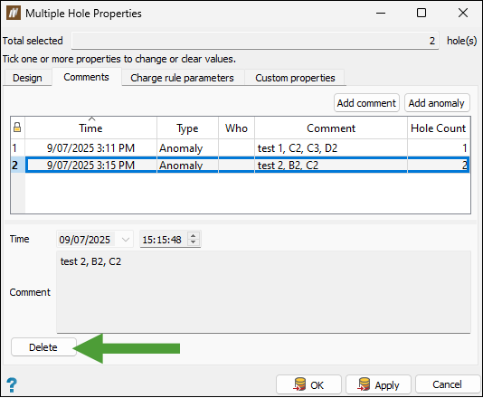
Tip: Select the blast and go to the Analysis tab > Report group >  Blast Summary Report > Anomalies tab to check the information for all anomalies recorded for the given blast.
Charge rule parameters
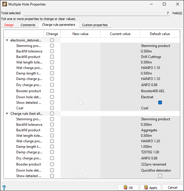
Use the Charge rule parameters tab to view and modify the charge rule properties for the selected holes. This allows you to make small modifications to how holes are charged, without having to clone or rewrite the charge rules.
To edit the charge rule parameters for the required holes, follow these steps:
-
Select the required holes in the view window.
-
Enter the Multiple Hole Properties panel and click on the Charge rule parameters tab.
-
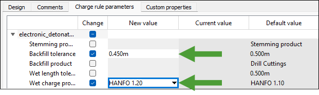
Select the checkbox in the Change column corresponding to the parameter that you want to edit.
-
Depending on the type of parameter that you selected, enter the new value or select the required option from the drop-down in the New value column.
-
Click OK or Apply to save the changed charge rule properties.
BlastLogic will display the values that you have applied in the Current value column.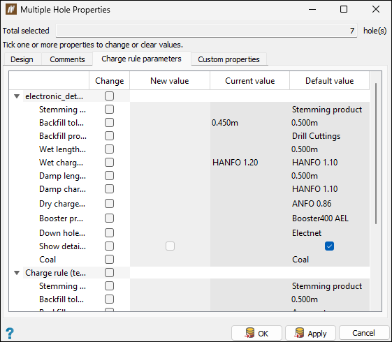
Optionally, to run the charge rule with the updated parameters, choose the required holes and navigate to the Charging tab > Design group and select
 Update charge plans (see Update Charge Plans for details).
 Note: The values shown in the Default value column will be used for the charge rule if you do not specify any new values. To revert to the default value, select the checkbox in the Change column corresponding to the parameter to which you want to reassign the default value, and enter the value in the New value column. Confirm by clicking OK or Apply.
See also: Create Charge Rule
Custom properties
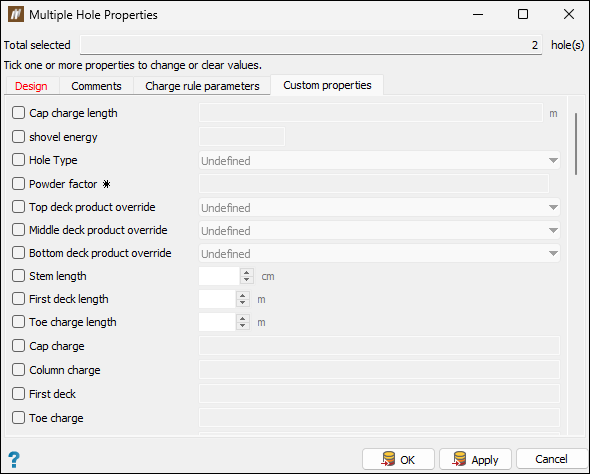
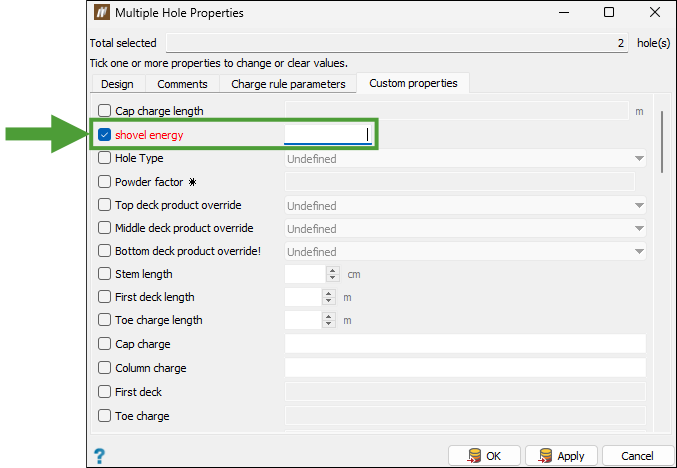
Use the Custom properties tab to view and modify custom hole properties for the selected holes.
To edit custom properties of multiple holes, follow these steps:
-
Select the required holes in the view window.
-
Enter the Multiple Hole Properties panel and click on the Custom properties tab.
-
Select the checkbox corresponding to the required property to enable editing.
-
Depending on the property type, select the required option from the drop-down or enter the value manually.
-
Click OK or Apply to save your changes. BlastLogic will apply these custom property settings to all selected holes.
