Acquiring scans
The  Acquire tab appears after a connection to a scanner has been established and allows you to acquire scans based on the current setup configured in the
  Setup tab.
|
|
|
Figure 7-28 Acquire tab |
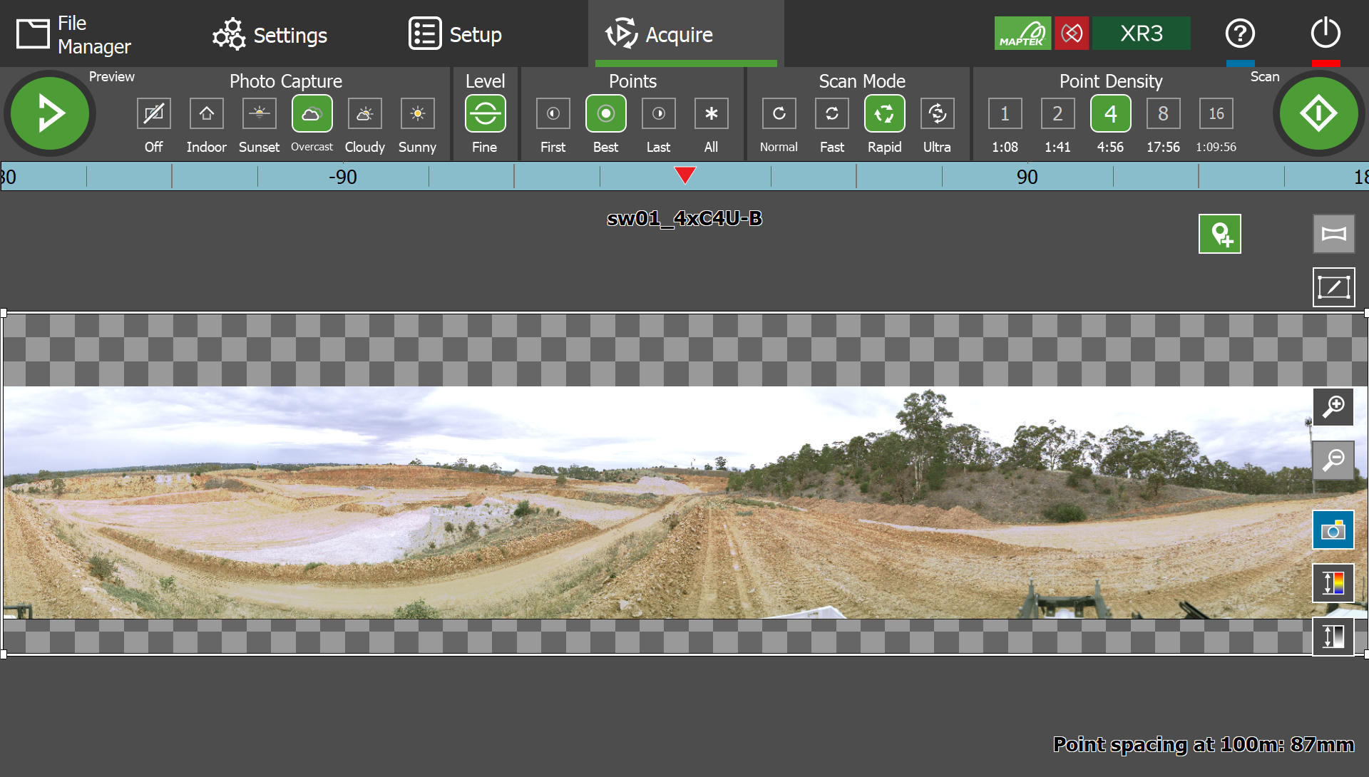
A typical workflow for acquiring scans involves the following:
-
Selecting scan settings from the toolbar at the top. See Selecting scan settings for information on each setting.
-
Selecting a region to scan, either the full extents or a smaller region. See Selecting a region to scan for detailed instructions.
-
Taking a preview. See Taking a preview for details.
-
Acquiring scans. See Taking scans for details.
Additionally, the in-viewer controls can be used to perform special functions such as updating the GPS coordinates, taking multiple backsight scans, or dual-window scans. See Viewer controls for details.
Selecting scan settings
The following settings can be chosen in any order prior to taking a preview or scan.
Photo Capture
The Photo Capture settings control the camera exposure level.
Note: Photo capture controls are only displayed for scanners equipped with a camera. The options displayed vary between scanner models.
|
|
|
Figure 7-29 Photo capture setting for aboveground conditions |
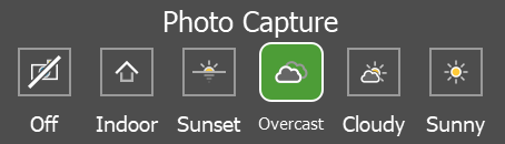
Scanners equipped with cameras for aboveground conditions provide exposure levels ranging from  Indoor, which should be used for the dimmest lighting conditions, to
  Sunny, for the brightest conditions.
-
Select the exposure level that best matches the current lighting conditions.
Tip: If you are unsure which setting to use, take a preview to get an idea of the effect of the current exposure setting, then adjust the setting as required.
-
Select
 Off to turn the camera off.
Photo capture with SR3 scanners
SR3 scanners use a dual-mode exposure system for aboveground and underground photo imaging.
-
Switch between aboveground and underground settings by toggling the
 Aboveground / Underground button.
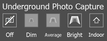
The underground settings range from range from  Dim (highest exposure level) to Indoor (lowest exposure level). Depending on the point density selected, some options may be disabled. This is because lower point densities cause the scanner head to traverse too rapidly to allow sufficient light into the camera aperture.
|
|
|
Figure 7-30 Underground photo capture settings for SR3 scanners. |
Tip: In dim light conditions, use a higher point density and a slower scan mode for better exposures.
Level
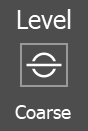
The Level button toggles the levelling resolution, as follows:
|
|
Fine levelling enabled. The scanner will perform a pre-scan head traversal to determine its inclination and apply a level correction. Fine level correction has a resolution of 20″ increments. |
|
|
Fine levelling disabled; coarse levelling will be applied. Scanning will commence directly after initiating the scan. Coarse levelling has a resolution of 1° increments. |

Tip: Fine levelling is enabled by default. Ensure that the scanner isn’t tilted more than 5° off the vertical axis to allow accurate auto-levelling.
Scan filenames include a letter code to indicate the levelling applied, as follows:
-
L (level): Scan acquired with Fine levelling.
-
U (unlevel): Scan acquired with Coarse levelling, or the scanner was tilted more than 5° off its vertical axis.
See Scan file naming for more information on scan file naming conventions.
See also: Level correction
Points
The Points setting controls which point returns are saved with the scan when more than one return is picked up along a given scanning beam path.
|
|
|
Figure 7-31 Points setting |
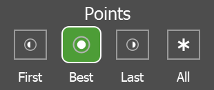
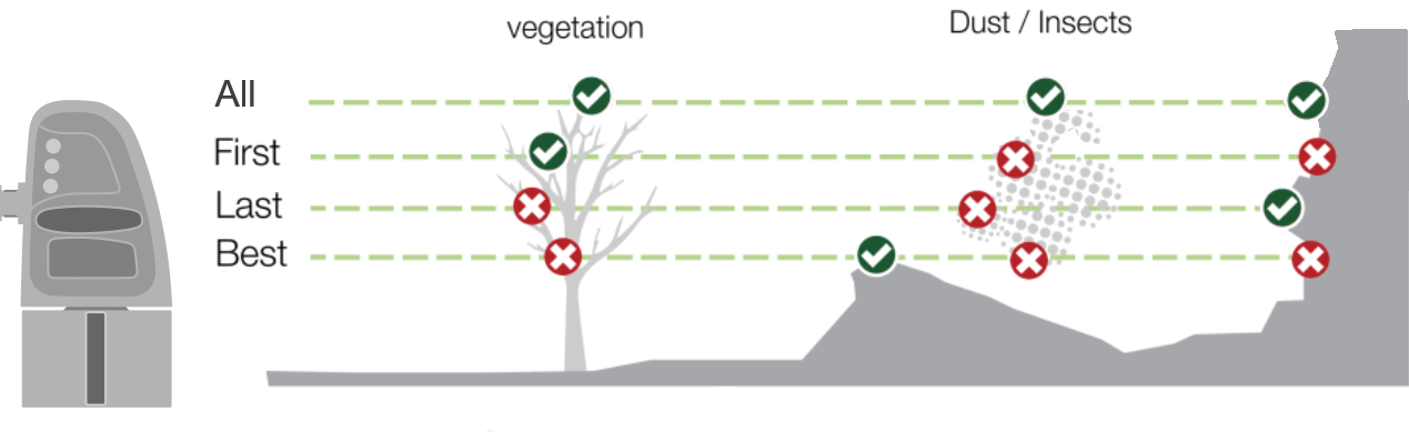
Choose the setting that provides the cleanest point cloud for the site conditions, as follows:
-
First: Store the first or closest point returns. Foreground occluders such as vegetation or dust may predominate in the resulting scan.
-
Best: Store the strongest point return. This uses an intelligent algorithm to select the best return and works well in most conditions.
-
Last: Store the last point return. This option may improve results when scanning through vegetation, light dust, insects, or snow.
-
All: Save all point returns.
Note: Selecting All may produce point clouds with excessive data and large file sizes. Use only when acquiring all points is necessary. Scans that save all points can be filtered in PointStudio using the Multi-Return Type filter.
|
|
|
Figure 7-32 Scan point selection in various scenarios. |
See also: Scan point selection
Scan Mode
The Scan Mode setting sets the laser’s pulse rate. The higher the pulse rate, the higher the scanning speed. You can consult the acquisition rates for you scanner model in Laser rangefinder.
|
|
|
Figure 7-33 Scan mode setting |
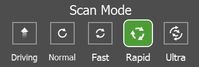
Select a scan mode that provides the best results for the distance or material being scanned:
- Normal (or Fast for SR3 scanners) provides the highest quality results and the maximum range performance.
- Ultra offers the highest speed at the expense of maximum range.
- Driving mode appears when connected to Maptek Drive. The scan mode speeds for driving scans are determined by the Driving scanning speed setting under
 Settings > Configuration.
Tip: When you have selected a region to scan, an estimate of the scanning times for the given Scan Mode are displayed under the Point Density setting options.
-
Scan mode for more information on scan mode
-
Range versus reflectivity for graphs of range versus reflectivity at different acquisition rates for your scanner model
Point Density
The Point Density setting sets the scanning resolution.
|
|
|
Figure 7-34 Points setting |
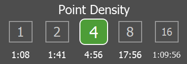
The lowest point density (1) results in the quickest scans, but with the largest spacing between points. The highest point density (16) results in the highest resolution scans, but at the expense of scanning time. Higher point densities also result in larger scan files.
Tip: The horizontal and vertical spacing between points halves for each increase in point density. So a point density of 2 has twice as many points in both the horizontal and vertical directions as a point density of 1; a point density of 4 has four times as many points, and so on. See Scan point density to get an indication of the theoretical maximum point count for each point density setting.
Tip: The approximate point spacing at 100 m resulting from the selected point density is displayed at the bottom of the viewer.
Note: SR3 scanners only support point densities 1, 2, 4, and 8.
Note: When Scan Mode is set to Driving, the point density is fixed to 2 and cannot be changed. Scan Direction is shown instead of Point Density.
See also: Point density
Scan Direction
The Scan Direction setting sets the fixed orientation of the scanner head while acquiring a Driving scan.
Note: This setting is only available when connected to Maptek Drive and Scan Mode is set to Driving.
|
|
|
Figure 7-35 Scan direction setting |
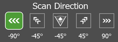
The scan direction is a clockwise angle relative to the forward direction of the vehicle. For example, to set the scanner to face out to the right side of the vehicle you would set a scan direction of 90°.
-
To set a custom scan direction, tap the
 button and enter a value.
Note: The Scanner to forward offset setting determines the scanner direction relative to the vehicle’s forward direction. See Configuring scanner and Drive vehicle mount offsets for details.
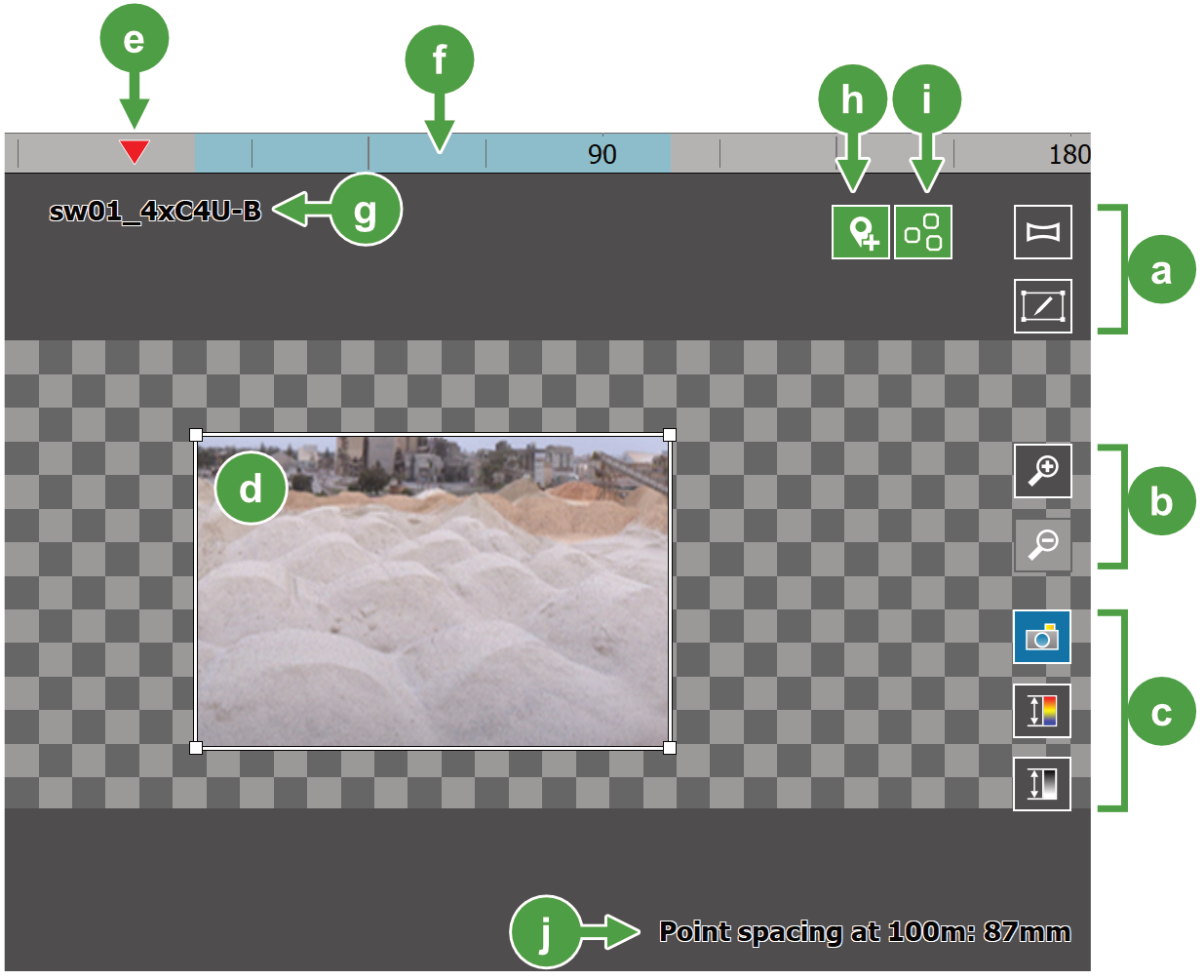
Viewer controls
The Acquire tab viewer allows you to define the area to scan and displays scan data as it is acquired. Figure 7-36 identifies the main features and controls of the viewer.


Selecting a region to scan
You need to select a region before taking a preview or scan. You can either select the full extent, or define a smaller window.
Selecting the full extent
To select the full extent, tap the  (Full extent) button in the viewer. The maximum scanning extent will be captured, i.e. 360° horizontally, and the maximum vertical extent supported by the scanner.
Tip: Take a preview using the full extent, and then refine the region to a smaller window for the scan if required.
Defining a scanning window
To define a scanning window:
-
Tap the
 (Define window) button in the viewer.
 -
Define a window in either of the following ways:
-
Drag a window on the scan area.
-
Drag an extent on the azimuth extents bar. A scanning window will be defined with the selected horizontal extent and the full vertical extent.
-
-
Adjust the window by dragging the edge or corners.
Tip: To clear the scanning window, tap the azimuth extent bar or tap the button.
Taking a preview
A preview is a quickly acquired image of the scanning region, which can then be used to further refine the region to scan or adjust the camera exposure settings. For scanners equipped with a camera, a photographic image is acquired. For scanners without a camera, a low-resolution scan is acquired.
To take a preview:
-
If using a scanner equipped with a camera, select an appropriate exposure level from the Photo Capture (or Underground Photo Capture) settings. The other scan settings do not affect previews.
-
Select a region to scan.
-
Tap
to select the full extent. -
Tap
to define a smaller scan window.
See Selecting a region to scan for more information.
-
-
Tap the
 Preview button to take the preview.
Taking scans
You can take a scan as soon as you have selected a region.
-
Tap the
 Scan button to start scanning using the current scan settings.
When scanning, a progress indicator appears that includes the remaining time to complete the scan.

After a scan has been acquired, it appears in the Scans list in the  File Manager tab. From here you can view the scan and perform other operations including file management and queries. See File management and Viewing scans for more information.
Pausing, resuming, and cancelling scans
You can pause or cancel a scan (or preview) that is in progress. Pausing a scan can be helpful to allow obstacles such as vehicles or dust to disappear before resuming.
-
Use the controls that appear on the progress indicator to control scanning, as follows:

Pause scanning 
Resume scanning 
Cancel current scan
Adding scans
You can queue additional scans with different regions and settings while a scan is in progress. Scanning for each successive scan in the queue will commence when the previous scan is complete.
To queue scans while a scan is in progress:
-
Select a new region to scan.
-
Adjust the scan settings as required.
-
Tap the
 Scan button.
You can repeat this process multiple times while scanning is in progress.
Repeating scans
Any scan in the scan queue, including a scan in progress, can be duplicated and added to the scan queue.
To repeat a scan:
-
Select the scan in the queue that you want to repeat by tapping its progress indicator. The
Scan button is replaced with the  Repeat Scan button.
 -
Tap
Repeat Scan to duplicate the scan and add it to the queue. Tap repeatedly to add more duplicates to the queue.
Scanning from a new location
For stationary setups, you need to update your location information whenever the scanner moves.
-
For survey jobs, switch to the
Setup tab and update your location and backsight information as required. -
For defined name setups, you can simply tap the
 (New setup) button in the viewer on the Acquire tab. Alternatively, switch to Setup > Defined name and then switch back to the Acquire tab.
