Surface
Source file: create-surface-group.htm
The Surface group tools of the Create tab enable you to create surfaces ![]() from scans and point selections by various methods that are suited to different situations.
from scans and point selections by various methods that are suited to different situations.

|
|
Topographic Surface (Alt+2) Create a surface from a plan view perspective. |
|
|
Scan Surface (Alt+N) Create a surface from a connected points selection (see Scan). |
|
|
Spherical surface (Alt+I) Create a surface from a spherical reference grid. |
|
|
Complex 3D Surface Create a surface modelling complex areas. |
|
|
Poisson Surface Create closed solid surfaces. |
|
|
Combination Surface Merge selected surfaces into one. |
|
|
Extrusion (Alt+X) extrude surfaces from lines or shapes. |
|
|
Offset Surface create a surface offset from a selected object. |
|
|
Fusion Surface (Alt+Y) Fuse multiple surfaces, retaining the most detailed where they overlap. |
Topographic Surface
The Topographic Surface tool (Alt+2) enables you to create a surface from a scan, or a group of scans or surfaces from polygons.
This tool
works in the XY plane. That is, it triangulates straight down. This means
that if there are areas of undercut walls, these will not be modelled
accurately
Run this tool after scans have been appropriately registered and filtered. See Position and Filter.
-
To create a topographic surface:
-
On the Create tab, in the Surface group, click
 Topographic Surface.
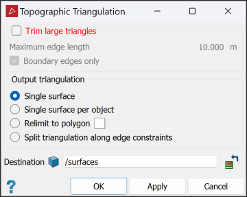
- Select Trim large triangles to eliminate long, incorrectly generated triangles. Enter Maximum edge length to define the maximum size of triangles being created. Select Boundary edges only to restrict trimming to large boundary triangles.
-
Select an Output triangulation surface type by selecting one of the following:
- Single surface: Creates a single surface from the selected objects or scans.
- Single surface per object: Creates a single surface for each selected object or scan.
- Relimit to polygon: Constrains the model to a polygon, for example a pit boundary. Drag the polygon into the field that appears.
- Split surface along edge constraints: Splits the surface into separate objects based on any lines or polygons selected in the project explorer when the surface is created.
-
Ensure the scan data is highlighted in the project explorer.
-
Click OK.
The surface is saved in the
surfacescontainer by default. You can change this in the Destination field. -
Note: Once the surface has been created, it may require despiking. See Despike.
|
|
|
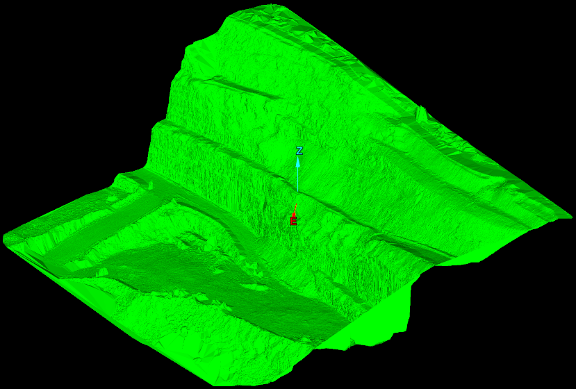
A topographic surface of a pit relimited to a polygon. |
Scan Surface
The Scan Surface tool (Alt+N) enables you to create a surface from a single scan, based on point connections made with the connection tools in the Scan group of the Position and Filter tab. This can be helpful for modelling irregular shapes such as truck trays and loader buckets.
-
To create a scan surface:
-
Using
 Connect or
  Smart Connect, connect the points in the scan you want the surface created from.
Tip: Because the smart connect, connect and disconnect tools act on point selections, you can edit connections manually if necessary.
-
On the Create tab, in the Surface group, click
 Scan Surface.
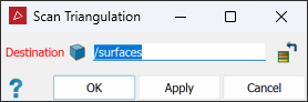
-
Select the connected scan created with Connect or Smart connect to triangulate.
-
Click OK or Apply.
-
The
surface is saved in the surfaces
container by default. You can change the container in the Destination field.
Spherical Surface
The Spherical Surface tool (Alt+I) enables you to create a surface based on a spherical grid instead of the XY plane. This is particularly useful for modelling overhanging surfaces.
Run this tool after scans have been appropriately registered and filtered. See Position and Filter.
-
To create a spherical surface, follow these steps:
-
With the scan loaded in a view window, press P to put it in Plan View Mode.
-
Select the scan data in the project explorer.
-
On the Create tab, in the Surface group, click
 Spherical Surface.
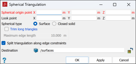
-
Select the required Spherical type from Surface or Closed solid.
-
Enter coordinates or click in the view window to define the Spherical origin point. This is the centre point for the spherical grid.
-
If you chose Surface at step 4, enter a value or click in the view window to select the Look point. This defines the radius of the spherical grid.
The origin and look point are displayed in the view window.
Note: If you are modelling only one scan, the spherical origin and look points are initially set to the origin of the scan and backsight direction by default.
NoteThe spherical surface tool will display transient geometry, depending on the selected Spherical type.
-
Surface will show a red arrow from the origin to the look point and arc behind the arrow, with a radius equal to the arrow’s length centred on the origin. This is useful at step 8.
-
Closed solid will show a sphere of a fixed size, which can be ignored.
-
-
Press Z to put the view in Z Up Mode, then rotate the view so that it is side on.
-
Alter the Z value of the Spherical origin point so that the red arrow is perpendicular to the wall.
Tip: Copy the Look point Z coordinate.
-
Select Trim long triangles and enter a Maximum edge length if you want to avoid long, incorrectly generated triangles.
-
Select Split surface along edge constraints if you want to split the surface into separate objects, by any lines or polygons selected in the project explorer when the surface is created. This option can be of use as a 'cookie cutter' when producing windows or a mine portal.
-
Click OK.
The
surface is saved in the surfaces
container by default.
Note: Once the surface has been created, it may require despiking. See Despike.
|
|
|
|
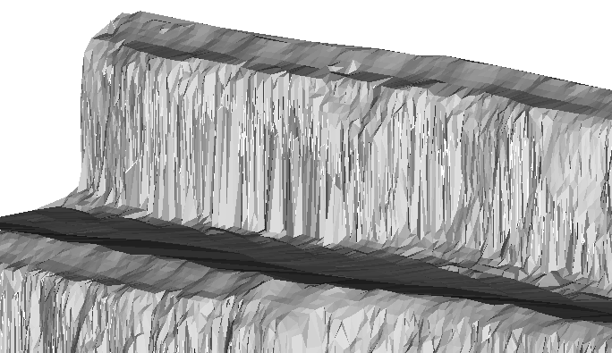
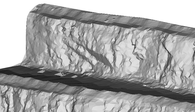
A topographic surface (left) and a spherical surface (right). |
|
Complex 3D Surface
The Complex 3D surface tool provides a simple solution for creating surfaces from point clouds where the existing methods do not adequately model the nuances of the actual ground or surface. The method only requires input of a guide to the smallest feature size, with which it will build the surface based on points within proximity of each other, regardless of orientation. This approach is good for detecting and including even small indents, overhangs and caves or holes that other surfacing methods would miss, and for modelling complex underground areas which include a number of pillars or interconnected tunnels.
-
To create a complex 3D surface, do the following:
-
On the Create tab, in the Surface group, click
 Complex 3D Surface.
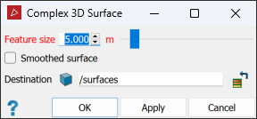
The Complex 3D Surface tool panel will open.
-
Set the desired Feature Size.
Note: Holes can occur in the model if the feature size guide is so small that the procedure cannot find a neighbouring point close enough to connect to. Larger feature sizes will result in fewer holes in the surface, but may also result in spike artefacts and less detail representing the true shape of the stope or ground.
Tip: Use a feature size that is a little larger than the holes you want to fill, but a little smaller than the size of features you want to keep.
-
Select Smoothed surface to minimise spikiness in the resulting surface.
Note: If surface smoothing is used for a large feature size, there will be less detail in the resulting surface.
-
Click OK or Apply.
A surface called Triangulation of <object name> or Smoothed triangulation of <object name> is created in the
surfacescontainer.Note: Where surfaces are created from multiple objects, they are named either Triangulation or Smoothed triangulation.
-
Inspect the new surface in a view window and decide whether to run again with different parameters.
Tip: Run the tool once with Smoothed surface cleared, and again with Smoothed surface selected, then compare the two results.
-
Click Cancel or
 when finished.
-
|
|
|
A Complex 3D surface |
Poisson Surface
Source file: create-surface-group.htm
The Poisson Surface tool uses the Poisson technique to create closed solids of underground voids.
The Poisson Surface tool has the following advantages:
- Is resilient to noisy data and misregistered artefacts.
- Performs quick calculating and rendering processes.
- Predicts where missing scan points should be and fills in those voids.
- Detects any extra unwanted points and ignores them for the surface reconstruction.
-
To create a Poisson surface, follow this procedure:
-
On the Labs tab, in the Create group, click
 Poisson Surface.
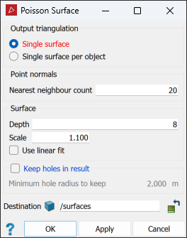
-
Under Output triangulation choose how to surface your selection. Select from:
- Single surface
- Single surface per object
-
Under Point Normals, in the Nearest neighbour count field, enter the number of nearest neighbouring points to use for the surfacing calculations.
- A larger count will make the surface smooth out more but you'll potentially lose sharpness around complex features.
- A lower count will make the surface appearance coarser.
Tip: In most situations, a Nearest neighbour count in the range of
3—20is sufficient. -
Under Surface you can configure the parameters that affect the resulting surface creation.
- Depth will determine the triangulation size used.
Lower values are sufficient for smooth surfaces with minimal noise.
Higher values manage noise better, for a more consistent surface.
-
If the triangles are too big, try increasing Depth by
1. If the triangles are too small, decrease Depth by1. Repeat until the result is satisfactory. -
A Depth value between
8and16will typically produce the optimal balance between surface clarity and detail. - Scale defines the maximum feature size the tool will process.
- Increasing Scale will cover larger gaps and will completely close the ends of a tunnel, creating a closed solid. If Scale is too high it will increase the base triangle size of the surface it's creating, resulting in larger bulges at the ends of tunnels. This can cause it to lose some resolution on the walls.
- Decreasing Scale might only triangulate the walls. If Scale is too small, the algorithm might not even triangulate all the walls.
- Select Use linear fit if the surface reconstruction is to use linear interpolation to estimate the positions of the iso-vertices.
Tip: If you double Scale, increase Depth by
1to keep the triangles the same size and retain fine detail.
Tip - Depth will determine the triangulation size used.
-
Click OK or Apply.
-
|
|
|
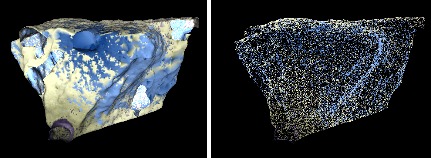
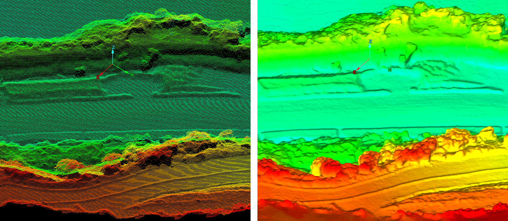
In the above example, the scan (left) had all its voids (black areas) completely filled in (right) by using the Poisson surface tool. The details are preserved and edges are smoothed out. |
Combination Surface
The combination surface tool enables you to merge selected surfaces into one single surface or closed solid.
-
To create a combination surface:
-
On the Create tab, in the Surface group, click
 Combination Surface.
 -
Select the required Surface type option from the following and use the relevant procedure below:
-
Topographic: Creates new surfaces or closed solids based on different ways of combining the original topographic surfaces
-
Closed solid: Creates new closed solids or volumes, based on different ways of combining the original closed solids.
-
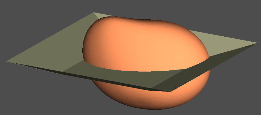
Solid and topography: Creates new closed solids or volumes by trimming a closed solid with a topography. You can choose to retain the portion above or below the topography, or both.
-
-
Expand below for further instructions, per your selection.
-
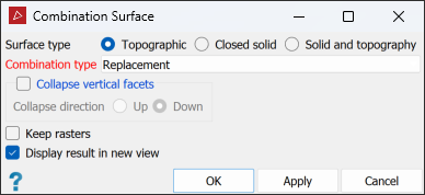
Select or clear Collapse vertical facets as required. If selected, choose a Collapse direction.
See step 3 of Fix Surface.
-
Select the required Combination type from the drop-down list.
- Lowest: combines the lowest parts of all surfaces.
- Replacement: replaces parts of the largest surface with smaller surfaces.
- Highest: combines the highest parts of all surfaces.
- Intersection solid: creates a closed solid between the highest and lowest points of the two intersecting surfaces.
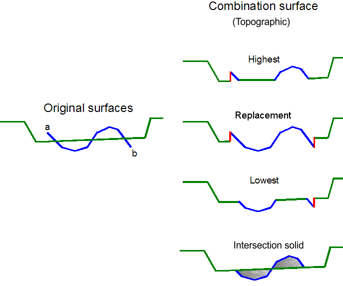
Note: The red lines in the image above indicate where surfaces do not meet at the boundary of the updated area. Vertical triangles are added to ensure the resulting surface is continuous.
-
Select Keep rasters to preserve the image or raster that is associated with the surface.
-
Select or clear Display result in new view as required.
-
Click OK or Apply.
-
Select the required Combination type from the drop-down list.
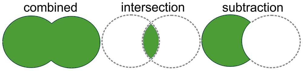
- Combined solid combines the original closed solids (volumes) into one closed solid (volume) enclosing all original closed solids (volumes).
- Solid intersection creates a new closed solid (volume) where the original closed solids (volumes) overlap.
- Solid subtraction creates a new closed solid (volume) where the first object has any overlap with a second object removed from its shape.
-
Select or clear Display result in new view as required.
-
Click OK or Apply.
Note: Collapse vertical facets and Keep rasters are not available for this surface type.
-
Select the required Combination type from the drop-down list.
- Keep Solid Above: to keep only the top part of the solid.
- Keep Solid Below: to keep only the bottom part of the solid.
- Keep
Solid Above and Below: to keep both, the top and the bottom part of the solid as two objects in the same view.
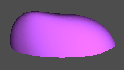
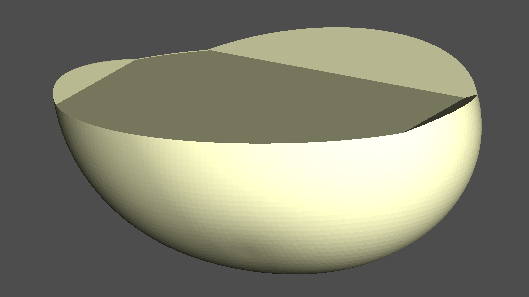
Result of keeping the top portion of the solid (left) and the bottom portion of the solid (right).
Result of keeping the top and bottom portions of the solid.
Note: Collapse vertical facets and Keep rasters are not available for this surface type.
-
Select or clear Display result in new view as required.
-
Click OK or Apply.
A new surface
is created and stored in the surfaces
container.
Extrusion
The Extrusion tool (Alt+X) enables you to create extrusions from objects such as polygons, lines, circles and more. This can be helpful, for example, for creating a surface from a line, or a cylinder from a circle.
-
To create an extrusion:
-
On the Create tab, in the Surface group, click
 Extrusion.
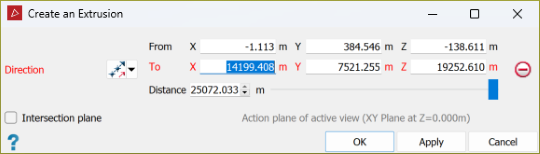
-
Select the object from which to create the extrusion.
-
Set the Direction of the extrusion by selecting one of the following options from the drop-down list and specifying its criteria:
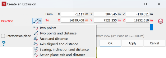

Two points
Define the direction and distance by specifying two points.

Two points and distance
Define the direction by specifying two points, then enter the distance.

Facet and distance
Make the direction perpendicular to a selected facet, then enter the distance.

Axis aligned and distance
Define the direction by an axis of the view window, then enter the distance.

Bearing, inclination and distance
Define the direction by a bearing and inclination angles, then enter the distance.

Action plane axis and distance
Define the direction by an axis of the action plane, then enter the distance.
You can populate parameter fields either by manually entering values, or selecting data in the project explorer or view window.
-
If the extrusion must be terminated by an intersecting plane, rather than by a defined distance, select Intersection plane and put the action plane in the required position.
Note: Intersection plane overrides the distance field.
-
Click OK or Apply. The extrusion will be saved in the
cad container.
-
|
|
|
|
An extrusion created from a circle. |
An extrusion created from a polygon and extruded to a plane. |


Offset Surface
The Offset Surface tool enables you to create a facet network at a fixed distance from the selected object. This can be helpful for CAD modelling of data.
You can make an offset surface from points, lines, loops or surfaces.
-
To make an offset surface:
-
On the Create tab, in the Surface group, click
 Offset Surface.
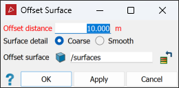
-
Enter the Offset distance for the surface.
-
Select a Coarse or Smooth surface. Smooth surfaces contain more triangles and will take longer to create.
-
The offset surface is saved in the
surfacescontainer by default. You can change this in the Offset surface field. -
Click OK or Apply to create the surface.
-
|
|
|
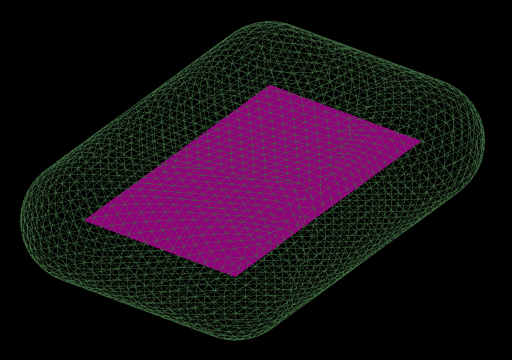
An offset surface created from a plane; the offset surface is displayed as wireframe. |
Fusion Surface
The Fusion Surface tool (Alt+Y) allows you to create a new surface of evenly sized triangles by following the original surfaces. Where surfaces overlap, the fusion surface will follow the most detailed surface. Fusion surfaces help to accurately model complex shapes or undercut faces in 3D.
-
To create a fusion surface, do the following:
-
Select the surfaces to be fused in the project explorer.
-
On the Create tab, in the Surface group, click
 Fusion Surface.
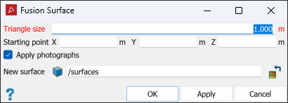
- Enter the Triangle size. All triangles produced will be this size.
-
Click on a point to start the fusion. This should be somewhere central with good overlap between the surfaces.
-
Select or clear Apply photographs as appropriate.
-
Click OK or Apply.
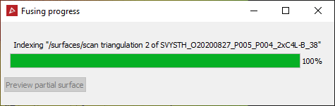
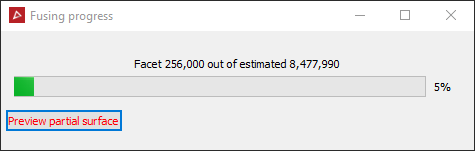
A progress indicator displays, showing the fusion progress.
-
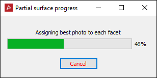
Click Preview partial surface to display the surface as it is created.
Tip: For best results, the triangle size must be greater than the figure used when filtering by minimum separation or topography. See Minimum Separation or Topography.
When indexing finishes the facets will be created.
Note: If no name was entered in the New surface field, clicking the preview button will result in a new surface being created.
-
Note: If the triangle size is too small, it can result in intersecting triangles. Always check with the surface validity tool afterwards. See Surface Validity.
