Register
Source file: register-dropdown.htm
The Register drop-down hosts tools for
The Register drop-down also hosts a tool for creating registration sequences for use with Maptek hand-held controllers and scanners.
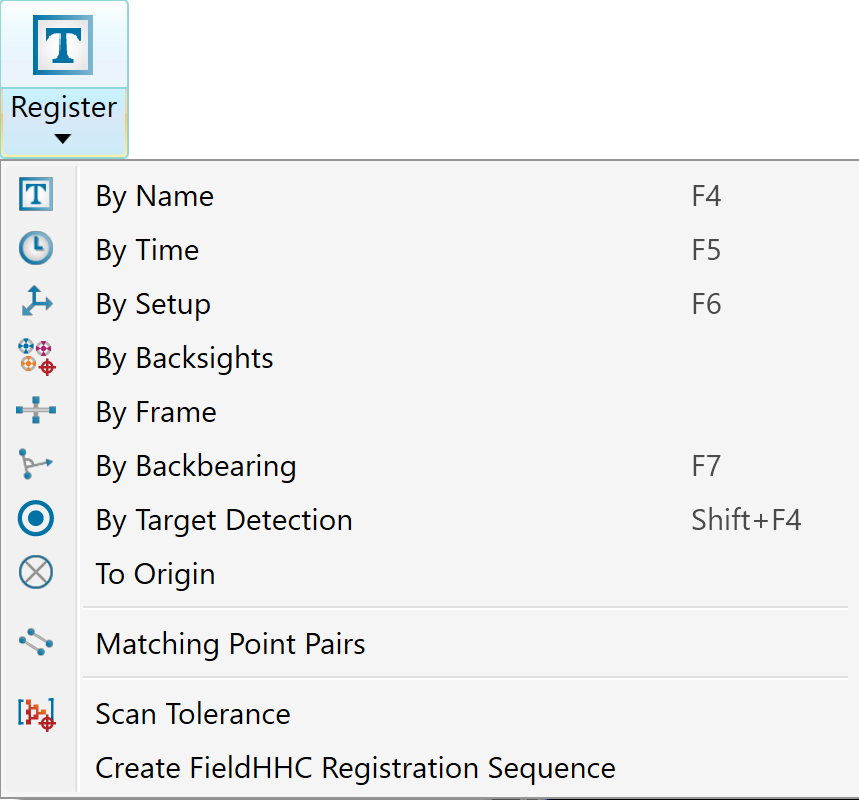
Expand below for details on each registration tool.
The By Name tool enables you to register scans that are named according to the R3 scanner naming convention (see R3 scan file name convention) by matching them with survey points ![]() .
.
-
Register by name requires that the location and backsight elements of the scan name exactly match the survey point and container names.
-
To position the scans in the correct survey datum, the survey control points text file, containing setups and backsights, must be stored in the
surveycontainer.
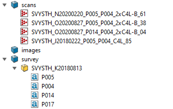
To register by name:
-
Highlight all scans

 to be registered in the project explorer.
 -
On the Position and Filter tab, go to the Register group. From the Register drop-down list select
 By Name. Alternatively, press F4.
Provided there are no naming errors, PointStudio will register the selected scans without further user input.
-
Visually check the scans for registration accuracy.
Tip: Before checking scan registration accuracy, colour the scans using the random intensity tint scheme (see Colour Scheme). This will assign a random colour to each scan, making it much easier to check the registration.
By time locates the scanner position by associating
scans to survey points ![]() data, copied from the GPS, with matching time stamps. Survey points are imported from a text or CSV file.
data, copied from the GPS, with matching time stamps. Survey points are imported from a text or CSV file.
Important: A scanner must be set to the correct time zone before taking a scan.
-
Import the survey points
 data. See Importing custom text and CSV file formats.
Ensure the Date-time column is defined on the Import panel.
ImportantThe survey data must have associated date-time information in the format dd-Mmm-yyyy hh:mm:ss.ss, where:
-
Seconds are optional
And
-
Month starts with a capital letter.
-
-
Highlight the scan

 in the project explorer.
 -
On the Position and Filter tab, go to the Register group. From the Register drop-down list select
 By Time. Alternatively, press F5.
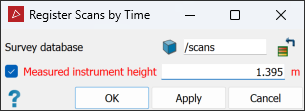
-
Drag the survey data from the project explorer into the Survey database field.
-
If the scanner elevation is incorrect in the scan, select Measured instrument height and enter the correct elevation.
This elevation can be either of the following, depending on the positioning reference used for the scan:
-
The distance above the ground reference marker, entered as a positive value.
Or
-
The distance below the GPS receiver’s phase centre, entered as a negative value.
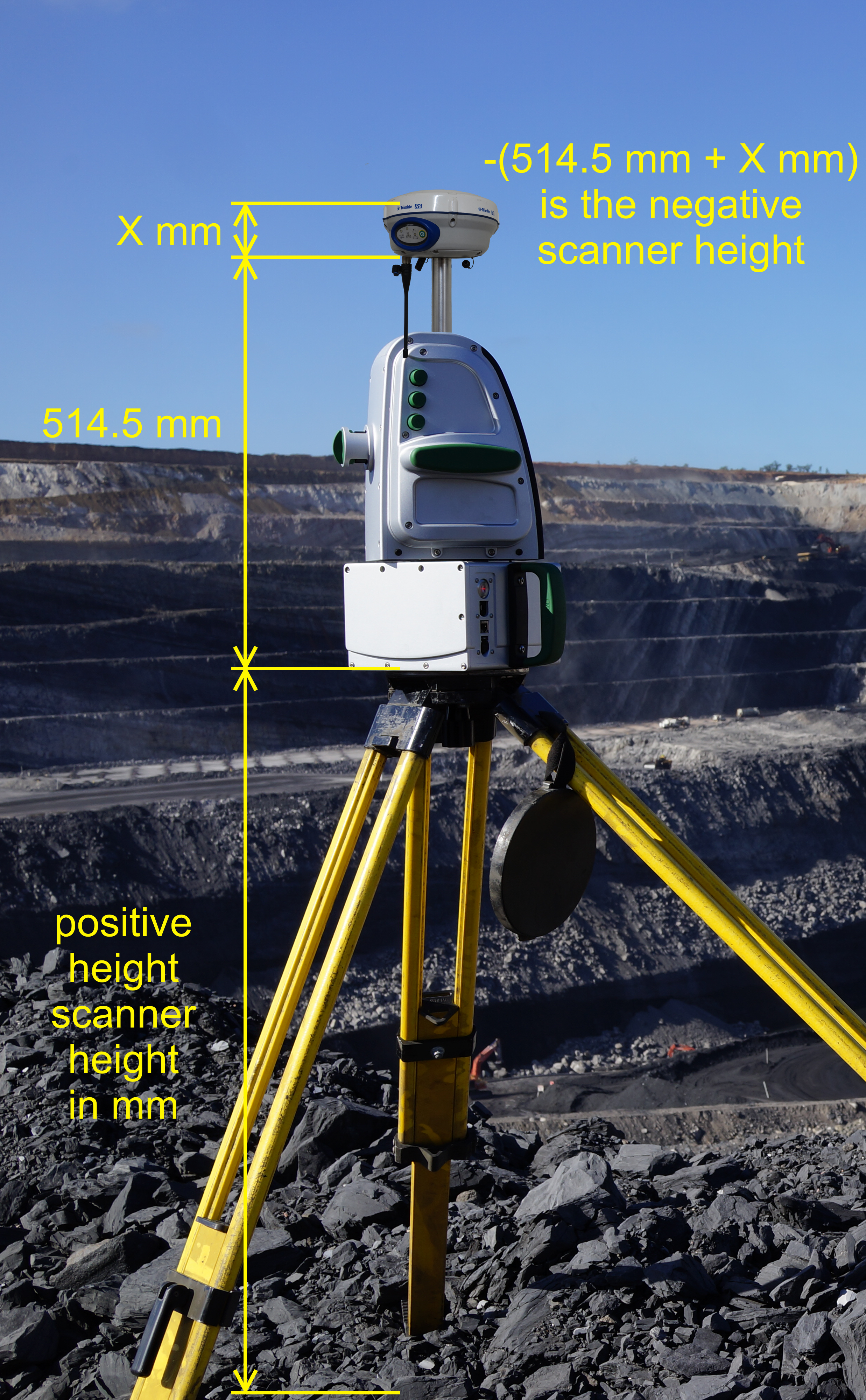
A possible scanner setup indicating both the ground offset and GPS offset distances.
-
-
Click OK or Apply.
The resulting registered scans can be used in global registration. See Global.
By Set-up enables you to correct any errors in the survey reference location, as follows.
-
On the Position and Filter tab, go to the Register group. From the Register drop-down list select
 By Setup. Alternatively, press F6.
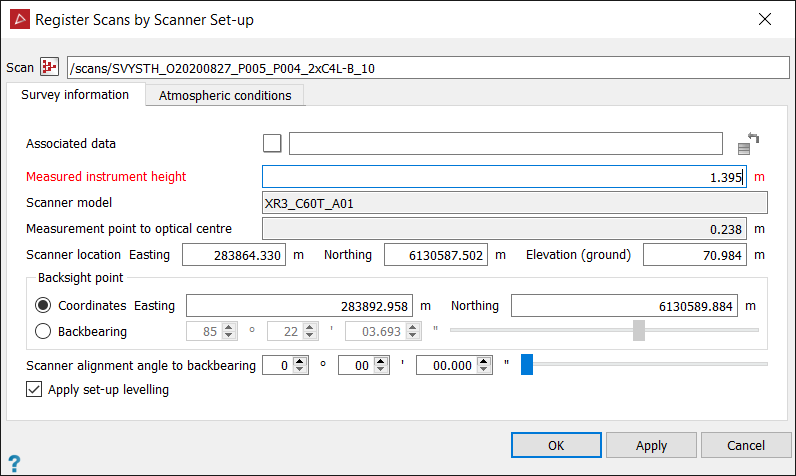
-
Drag the scan

 to be registered into the Scan
field. Some fields may auto-populate, depending on information contained in the scan data.
 -
Drag any associated data to be registered simultaneously into the Associated data field. Associated data is anything that is positioned relative to the scan you are registering, such as a limited extents scan at a different resolution.
-
Enter the elevation of the scanner reference point in the Measured instrument height field.
This elevation can be either of the following, depending on the positioning reference used for the scan:
-
The distance above the ground reference marker, entered as a positive value.
Or
-
The distance below the GPS receiver’s phase centre, entered as a negative value.

A possible scanner setup indicating both the ground offset and GPS offset distances.
-
-
Load the survey stations into a separate view window.
-
Select one of the Scanner location fields (Easting, Northing or Elevation) then click on the scanner location in the view window.
Tip: Use point selection
 mode to restrict picking to survey station points and prevent undesired
selections.
 -
Locate the Backsight point by one of the following methods:
-
Coordinates: Select either the Easting or Northing field, then click on a survey station.
Or
-
Backbearing: Enter the bearing from the scanner to the backsight point, if known.
-
-
If required, enter the Scanner alignment angle to backbearing measured clockwise from the scanner look direction to the backsight. This is the angular offset from the backsight to the look direction of the scanner.
-
If levelling information is available, the Apply set-up levelling option is selected. Clear this option to ignore set-up levelling.
-
If necessary, adjust the Temperature, Pressure and Altitude values on the Atmospheric conditions tab. This is only required if the scan range is over 1000 m, or for precision scanning.
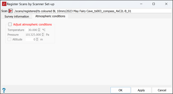
The temperature and pressure (or altitude) settings on the scanner controller improve the calibrated range accuracy, especially for long distances.
Range Approximate range shift per 10° C Approximate range shift per 60 mbar (or 400 m) 1000 m
10 mm
16 mm
750 m
7.5 mm
12 mm
500 m
5 mm
8 mm
250 m
2.5 mm
4 mm
Note: Scanner model and Measurement point to optical centre distance are read from the scan.
Accuracies of +/- 5° C for temperature and +/- 30 mbar for pressure are adequate to achieve conformance with the scanner specifications.
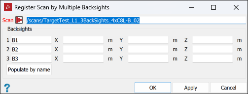
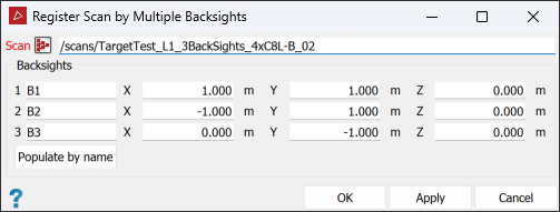
By Backsights enables you to edit or correct data labels or names and coordinates relating to multiple backsights that may have been used in originally defining the scanner position.
-
Import the survey points
 data. See Importing custom text and CSV file formats.
 -
Load the scan

 to be registered and the survey points in a view window.
 -
On the Position and Filter tab, go to the Register group. From the Register drop-down list select
 By Backsights.
 -
Drag the scan to be registered into the Scan field.
-
Edit the information in the Backsights fields, as required. If the survey stations used are in a survey station database, click Populate by name to automatically retrieve the positional data, based on their labels or names.
-
Click OK or Apply to finish.
|
|
|
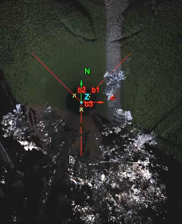
Replacing incorrect coordinates (top) with correct coordinates (bottom). |
|
|
|
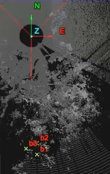
Original (incorrect) coordinates for backsights b1, b2 and b3 produced this layout. |
|
|
|
|
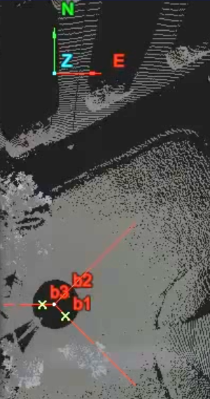
Real backsight locations (b1, b2, b3) identified here. |
Scan is now
registered to the new (correct) coordinates. |
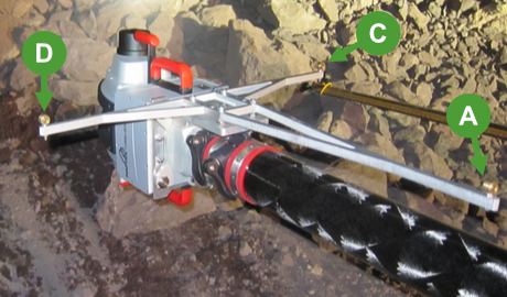
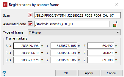
By Frame enables you to identify the scanner’s position in underground scans when the scanner is connected to a frame fitted with three markers. These markers are surveyed using a total station and the results are to be imported into PointStudio. The locations of the markers and the frame in relation to the scanner are constants embedded in the software.
This option supports frame attachments for obsolete and current model Maptek scanners.
-
To register by scanner frame setup, follow these steps:
-
Import the survey points
 data. See Importing custom text and CSV file formats.
 -
Display the data to be registered and the survey points in a view window.
-
On the Position and Filter tab, go to the Register group. From the Register drop-down list select
 By Frame.
-
Drag the scan

 to be registered into the Scan
field.
 -
Drag any associated data to be registered simultaneously into the Associated data field. Associated data is anything that is positioned relative to the scan you are registering, such as a limited extents scan at a different resolution.
-
Select the Type of frame used to take the scan from the drop-down list.
-
Click in the Frame markers fields and onto the corresponding markers in the view window, or manually enter the marker coordinates.
-
Click OK or Apply.
The resulting registered scans can be used in global registration. See Global.
-
|
|
|
An initial group of unregistered scans (left) automatically aligned (right). |
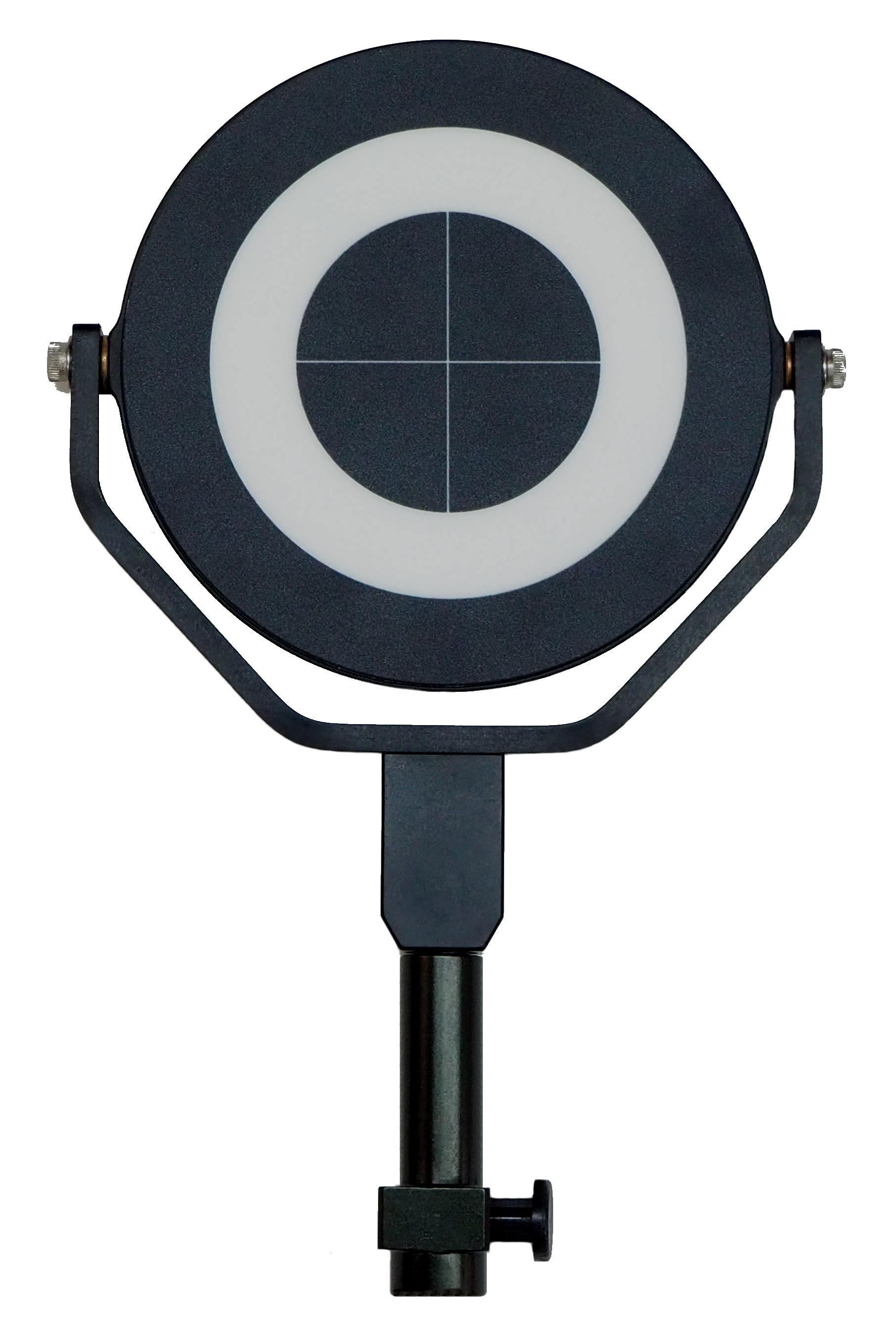
By Target Detection allows you to register scans taken without a GPS signal, such as in the underground mining environment, working in conjunction with the Matching Point Pairs tool (see Matching Point Pairs). The By Target Detection tool detects any Maptek proprietary targets that have been scanned (see Notes on scanning targets, below), then automatically imports their coordinates into the Matching Point Pairs tool to register scans, using the existing survey data. The Matching Point Pairs tool will calculate the final separation tolerances and register the scans.
-
Follow these steps to successfully detect targets and register scans:
-
Import the scans

 to be registered into PointStudio.
 -
On the Position and Filter tab, go to the Register group. From the Register drop-down list select
 By Target Detection. Alternatively, press Shift+F4.
 -
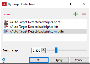
Select the scans in the project explorer and click
 .
.Tip: Only select the scans of the Maptek proprietary targets at this step to avoid unnecessary and ambiguous detections.
-
The default Search step value is
0.500, but this can be adjusted in the range0.100to2.000. If necessary, set a more appropriate value for the target locations and visibility.Targets that are further from the scanner are harder to detect, so smaller search steps will work better. Nearer targets are easier to detect; larger search steps can be used.
Tip: Try running the target detection tool with the default search step. If the results are unsatisfactory, adjust the search step as appropriate and repeat.
Note: Higher search step values will speed up the search process at the expense of accuracy. Lower values will produce a more accurate result but the process will take longer.
-
Click OK or Apply.
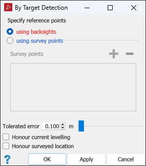
The tool will attempt to detect the targets. When three or more targets have been detected, a truncated Matching Point Pairs panel will open, retitled By Target Detection.
-
Under Specify reference points, select the preferred method of specifying reference points from the following:
- using backsights if you have backsighted to known survey points. The tool will use the scans’ metadata to extract the backsight details.
- using survey points if you have not already backsighted to known survey points. In this case you will need to provide the existing survey data. Highlight the survey points in the project explorer and click
 .
.
-
Set the remaining options:
-
If the scans are level, select Honour current levelling to allow translation of the data in any direction, but to restrict rotation to about the z-axis only.
-
If the data requires rotation, but not translation, select Honour surveyed location.
Note: Honour surveyed location is only available if all scans are from the same survey point.
-
-
Select the scans to be registered in the project explorer or active view window.
-
Click OK or Apply.
The register By Target Detection panel will open.
-
The scans will now be registered and display a summary in the report window.

Notes on scanning targets
-
At least three targets must be scanned for successful registration.
-
In taking the scans, the targets must be placed in locations that are in the line of sight of the scanner, but not facing the scanner perpendicularly.
-
The targets will ideally be within 40 m of the scanner.
-
Set the scanner scan at a high resolution. A resolution value of
8is recommended. -
Scan only a small area around the target.
|
|
|
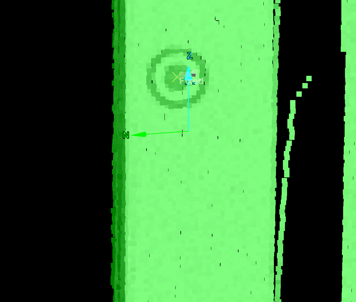
Maptek Underground Target (left). Example of a target detected in the scan (right). |
Via scanner internal compass
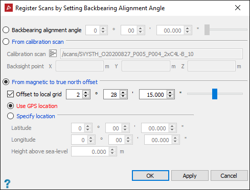
The From magnetic to true north offset
option can be used if the scanner has an in built compass and GPS receiver. Entering
the location and altitude of the scanner adjusts the compass reading from
magnetic to true north. More accurate adjustment may be possible if localised
information is available to provide a further Offset
to local grid.
-
Highlight the scans

 to be registered in the project explorer.
 -
On the Position and Filter tab, go to the Register group. From the Register drop-down list select
 By Backbearing. Alternatively, press F7.
-
Select From magnetic to true north offset.
-
Choose Use GPS location to utilise the data collected from the scanner's inbuilt GPS receiver.
-
Enter the mean Height above sea-level (+/-
50m). -
Click OK or Apply.
Or
Choose Specify Location and enter the latitude and longitude of the scanner location.
When using a vehicle mount
If the vehicle mount was used in conjunction with the Maptek Gen 3 scanners, the backbearing alignment angle must be set.
The scanner is mounted on the roof of the vehicle and is referenced against two points; the scanner position and a reference point on the vehicle (second GPS point). The scanner is not physically backsighted to the reference point, but the relationship between the scanner orientation and the vehicle is fixed and can be measured from the scanned photograph. The reference point is very short compared with the scanner range, which will result in alignment errors that must be corrected.
The backbearing
alignment angle is the relationship between the scanner orientation and
the reference point. Once known, the same correction angle can be applied
to each scan acquired from that vehicle.
-
Load the scan

 into a view window.
 -
Right-click on the scan and from the context menu and select Display panoramic data.
Note: If the scans do not have photographic data, right-click and select View scan from origin, pan to the area of interest and connect the scan. See Scan.
-
Rotate the image until the reference point (second GPS point on the vehicle) can be seen.
-
On the Position and Filter tab, go to the Register group. From the Register drop-down list select
 By Backbearing. Alternatively, press F7.
 -
Select From calibration scan.
-
Calculate the backbearing alignment angle:
-
Load the scan into the Calibration scan field (drag from the project explorer).
-
Click in the Backsight pointX field and click on the reference point in the photograph.
The tool will compute the angle between the scanner orientation and the reference point and display it in the Backbearing alignment angle field.
-
-
Click OK or Apply to apply this angle to the calibration scan.
Apply the backbearing alignment angle
If the backbearing alignment angle is known, it can be manually entered.
-
Highlight the scan

 to be registered in the project explorer.
 -
On the Position and Filter tab, go to the Register group. From the Register drop-down list select
 By Backbearing. Alternatively, press F7.
 -
Select Backbearing alignment angle.
-
Enter the angle.
-
Click OK or Apply.
Run the To origin tool to undo any translation, rotation or registering that has been performed on the selected scan or scans. This sets the scan origin to (0, 0, 0) and oriented to the Y axis.
-
To set scans back to their origins, select them then, on the Position and Filter tab, go to the Register group. From the Register drop-down list select
 To Origin.
The Matching Point Pairs tool enables you to position data with reference to reflectors, targets,
or common features. Multiple fixed points are used to tie the data to
be registered to the reference data. This tool can be used in conjunction with the ![]() Locate Reflectors tool. See Locating Reflectors.
Locate Reflectors tool. See Locating Reflectors.
-
On the Position and Filter tab, go to the Register group. From the Register drop-down list, select
 Matching Point Pairs.
-
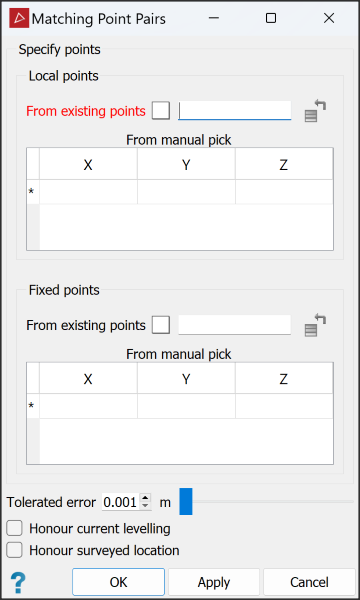
Specify the points to be matched in registering the scans. You can do this either from existing pointsets or by manually picking points. Expand below for each method.
 From existing points
-
Drag the container holding the located reflectors (or equivalent) into the Local points field.
-
Drag the container with the reference points into the Fixed points field.
 From manual pick
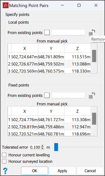
Either enter values into the cells for X,Y,Z coordinates of local and fixed points, or select the first available row of the relevant field, then click on the point locations in the view window.
Note: From manual pick allows the local and fixed points to be loaded in separate views. However, all local points must be in one view, and all fixed points must also be in one view.
Note-
Local points are points to be moved to align with the Fixed points. They can be defined using the
 Survey Points
or
  Locate reflectors tool. See Survey Points or Locating Reflectors.
-
Fixed points are the known reference points that have been created on the base data, which can also be a survey station database of reflectors.
-
You need at least three points in each of the local and fixed point sets
-
At least 50% of local points must have corresponding points in the fixed set, though point sets do not require an identical number of points within them.
-
-
Set the remaining options, as follows:
-
Tolerated error value as the final tolerated distance error of acceptable pair matches.
-
If the data is level, select Honour current levelling to allow translation of the data in any direction, but to restrict rotation to about the Z-axis only.
-
If the data requires rotation, but not translation, select Honour surveyed location.
-
-
Highlight the scans to be registered in the project explorer.
-
Click OK or Apply.
The data will move to its correct location.
The Scan Tolerance tool enables you to change the horizontal and vertical tolerance values for a scan or set of scans. These values override any previous values that may have been set.
Raw scan data may possess positional errors relating to many factors such as the scanner's precision and accuracy, environmental conditions and types of material being scanned. When used with Global registration, the scan origin is only allowed to move within an ellipsoid defined by the horizontal and vertical values of the scan tolerances.
-
To modify scan tolerances, follow these steps:
-
Select the scans

 whose tolerances are to be adjusted in the project explorer or in the view window.
 -
On the Position and Filter tab, go to the Register group. From the Register drop-down list select
 Scan Tolerance.
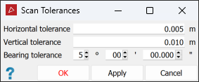
Note: Scan Tolerances displays the current values for a scan when the panel is initially opened. If multiple scans are selected, fields that differ between scans will be left blank.
-
Enter new values for the tolerances.
-
Press OK or Apply.
-
Tip: You can also change default scan tolerances in Preferences > Registration.
The Create FieldHHC Registration Sequence tool enables you to create .json files for the FieldHHC software to specify how to perform scan registration with the hand-held controller in the field.
-
On the Position and Filter tab, go the Register group, click Create FieldHHC Registration Sequence from the Register drop-down.
The Create FieldHHC Registration Sequence tool panel opens.

-
Click
 then browse to a location to save the
 .jsonfile. Enter a name and click Save. - Each row of the field is a step in the registration process. Configure the options for the first step per the following:
Type: Select the required registration type.
Register to apply Global Registration, accurately registering scans.
Initialise to apply Automated Initial Positioning, placing unregistered scans into roughly the right positions with respect to each other before applying global registration.
Sampling: Select the sampling level required.
Low. Use this setting when registering scans that have closely spaced points or consist of flatter surfaces with coarser data matching patterns. Low sampling provides faster initial results.
Medium. Use this setting in scenarios where nearby surface features are more prominent while also sampling sparse or distant scan points.
High. Use this to process the maximum amount of points. This mode is most often used in scenarios such as scanning from an elevated position or when scanning in voids where more detail is required to detect and combine matching features.
Translation: Select a translation constraint.
Free. Horizontal and vertical translation by any distance are both allowed.
Bounded. Horizontal and vertical translation are both allowed, but limited to set distance bounds. The bounds are set in the Manual bounds setting
Fixed. The scan’s location is fixed; translation is not allowed.
Rotation: Select a rotation constraint.
Free. Rotation is unrestricted. A scan can be both rotated around its vertical axis, and also have the tilt of its vertical axis adjusted.
Bearing. Rotation is only allowed around a scan’s vertical axis; tilting of the vertical axis is not allowed.
Horizontal Bounds: Enter the maximum permitted distance to move the scan horizontally.
Vertical Bounds: Enter the maximum permitted distance to move the scan vertically.
Minimum Range: Enter the nearest distance for points to be considered in the registration algorithm.
Maximum Range: Enter the farthest distance for points to be considered in the registration algorithm.
Connect: Select to join adjacent points from the selected scans. Similar to Smart Connect (see Smart Connect), but with degree of connectivity fixed at 0.1 m.
Detect Edges: Select to use detected edges in the registration.
-
Repeat for the second and subsequent rows.
-
Click OK or Apply to save the changes to the file.
