Components
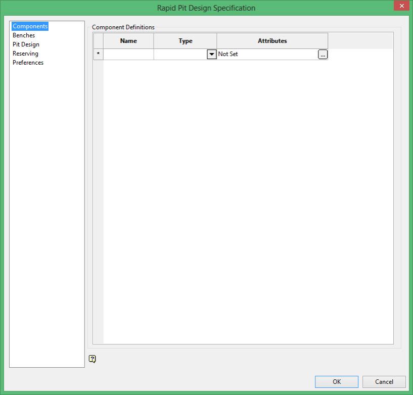
Component Definitions
Name
Enter a name for the component.
Type
Select either Block Model or Design Database from the drop-down list in the Type column.
Attributes
Click ![]() to access the panel for the selected component type ( Block Model Selection or Design Database Selection ).
to access the panel for the selected component type ( Block Model Selection or Design Database Selection ).
Block Model Selection
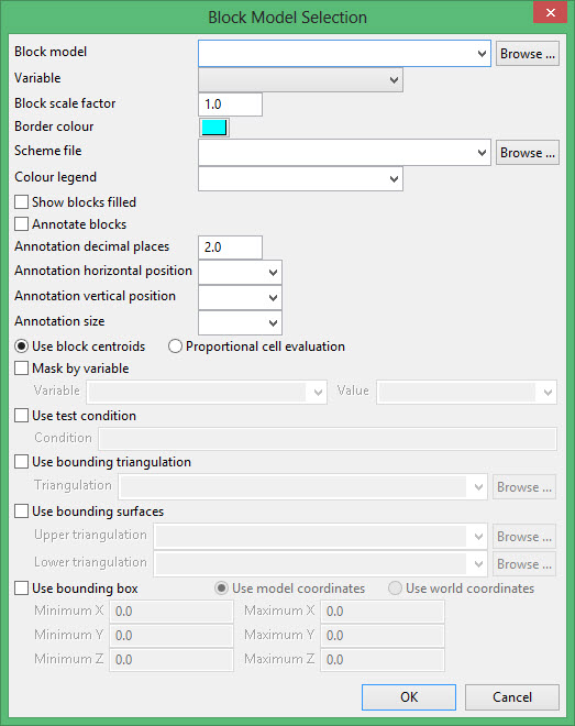
Block model
Select a block model. The drop-down list contains all block models found in the current working directory. Click Browse to select a file from another location.
Variable
Enter or browse for the variable that you want to display. The drop-down list contains all of the variables that were assigned to the block model when it was created.
Block scale factor
Enter the scale factor. Specifying a scale factor allows you to shrink the block markers to ensure that the edges do not overlap. The factor (or gap) is entered in plotter units. Valid values for the scale factor are between 0 and 1. A value of 1 will draw the blocks at the full size and a value of 0 will not draw the blocks at all.
Border colour
Pick a colour from the palette to use for the block borders.
Scheme file
Select from the drop-down list or browse to the .scd file which contains the block model legends.
Colour legend
Select the colour legend that you want to use.
Show blocks filled
Select this check box to show the blocks filled. If left unchecked, the blocks will be drawn without fill.
Annotate blocks
Select this check box to annotate selected blocks with their block value.
Annotation decimal places
Enter the number of decimal places that you want to use with your annotations.
Annotation horizontal position
Enter, in plotter units, the horizontal offsets for the trace annotations.
Annotation vertical position
Select the vertical position in the block for the annotation.
Annotation size
Enter, in plotter units, the size for the trace annotations.
Use block centroids
Select this option to include blocks of the block centroid is in the region. Note the entire block is included.
Proportional cell evaluation
Select this option to include those blocks that touch the region. When selecting blocks, all blocks that touch the region are selected.
Mask by variable
Select this check box to restrict the blocks by a block model variables. You will need to specify the variable, as well as a particular value.
For example, to restrict blocks to those where Material equals Ore, select Material as the variable (from the drop-down list) and enter Ore as the value. However, if you require all blocks that do not have this specified value, then enable the Reverse selection check box.
Use test condition
Select this check box to use a further constraint upon a numeric block model variable, such as Fe GT 10.0 (iron value greater than 10.0). The maximum size of the condition is 132 alphanumeric characters. A list of available operators/functions is provided in Appendix D of the Core Documentation.
Use bounding triangulation
Select this check box to restrict the blocks by a triangulation. This is useful when, for example, you want to evaluate reserves in a particular solid triangulation such as a stope.
Use bounding surfaces
Select this check box to restrict the blocks by bounding surfaces. Once the Block Selection panel has been completed, you will be required to select (from the screen) the top and bottom surface triangulations. Only blocks that lie in the overlapping sections, as viewed in plan view, of the surfaces are selected.
Use bounding box (block model coordinates)
Select this check box to restrict the estimation to those blocks whose centroids lie in a specified range of coordinates. Enter the minimum and maximum coordinates (in the X, Y and Z directions). These coordinates are offsets from coordinates at the origin of the block model.
Design Database Selection
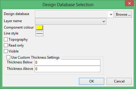
Design database
Select a design database from the drop-down list or browse to the dgd.isis file which contains the layer for the component.
Layer name
Select a layer name from the drop-down list.
Component colour
Select the component colour in which to display the component in Rapid Pit Design.
Line style
Select the line style by selecting from the palette.
Topography
Select this check box if the component is a topography or similar type object. Selecting this box will not allow reserves to be run on this component, thus making things faster.
Read only
Select this check box to make the component read-only, meaning that it cannot be permanently changed inside of Rapid Pit Design.
Visible
Select this check box to make the component visible inside of Rapid Pit Design. This can be toggled using the Properties window .
Use Custom Thickness Settings
Select this check box to setup custom thickness for a particular component. If a custom thickness is used, it will overwrite the global thickness in the properties window inside of Rapid Pit Design. Thickness below and Thickness above are defined in terms of number of benches.
Related topics
Related tutorials

