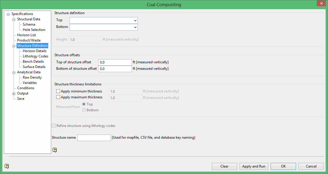
Structure Definition
Use Structure Definition to define the top and bottom of the structure that will be composited for each hole. The various methods all produce a top and bottom downhole depth per hole.
The methods available for both the top and bottom are by horizon, bench level, surface model, or by a height (vertical distance between the top and bottom). This can be modified by offsetting both the top and bottom by a vertical distance, and also a minimum and maximum thickness can be applied to the structure when it is applicable.
You are also able to refine the structure by lithology codes (rock type) which means that a search is made from the top and bottom of the structure to find the first interval respectively that match the rock code definition, for example, the first coal interval.
Structure definition
This section allows defines the top and bottom of the structure to composite for each drillhole. The various methods all produce a top and bottom downhole depth per drillhole.
Note: Options in the Horizon Details, Lithology Details, Bench Details, and Surface Details panes activate based upon selected Structure definition method(s).
Define Top or Bottom structures by:
-
Horizon
-
Bench Level
-
Surface Model
-
Vertical distance defined from the top or bottom
Top
These selections will control the top of the composite. The following options are available:
Horizon
The top of the composite coincides with the first interval of a given horizon.
Bench Level
The top of the composite coincides with a defined elevation. Levels are defined in the Bench Details pane.
Surface Model
The top of the composite coincides with the intersection of a defined surface. The surface is selected in the Surface Details pane.
Derived from Bottom
After selecting this option, enter a vertical Height.
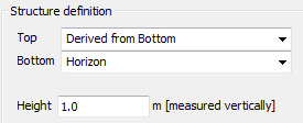
This option may be used in conjunction with any of the Bottom Structure definition options except Derived from Top. The result is an interval in each drillhole derived by relative thickness from a selected Horizon, Bench Level or Surface Model which defines the bottom of the composite.
Bottom
These selections will control the bottom of the composite. The following options are available:
Horizon
The bottom of the composite coincides with the last interval of a given composite.
Bench Level
The bottom of the composite coincides with a defined elevation. Levels are defined in the Bench Details pane.
Surface Model
The bottom of the composite coincides with the intersection of a defined surface. The surface is selected in the Surface Details pane.
Derived from Top
After selecting this option, enter a vertical Height.
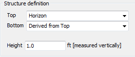
This option may be used in conjunction with any of the Top Structure definition options except Derived from Bottom. The result is an interval in each drillhole derived by relative thickness from a selected Horizon, Bench Level or Surface Model which defines the top of the composite.
If a Bench Level or Surface Model intercepts the drillhole outside the ultimate drillhole depth, then the part of the hole that is beyond the drillhole depth is considered missing lithology. This may or may not cause an error depending on how data is handled when defining Variables under the Analytical Data folder.
Structure offsets
E nter Structure offsets to offset the top and bottom definition by a vertical distance. Use these options to quickly simulate a simple loss or dilution. For example, without adding intervals to the input database, use Structure offsets to create grids which are a set distance, such as 10 centimetres, from roof and floor grids.
Top of structure offset
Enter the vertical distance to offset from the top of the structure.
Bottom of structure offset
Enter the vertical distance to offset from the bottom of the structure.
Structure thickness limitations
Optional Structure thickness limitations can force a minimum and/or maximum thickness if applicable.
Check Apply minimum thickness to define a minimum thickness requirement. Composited structures that are less than the specified thickness are increased in size to the minimum thickness value.
Check Apply maximum thickness to define a maximum thickness requirement. Composited structures that are greater than the specified thickness are decreased in size to the maximum thickness value.
Select whether the entered minimum or maximum values will be Measured from the Top or the Bottom of the structure.
Refine structure using lithology codes
Lithology codes can further refine the structure using the field in the database which was assigned the Rock Type synonym. If a different field was selected as the Rock Type field in the Schema panel, the field chosen in the Schema panel will override the field associated with the rocktype synonym in the database.
A search is made from the top and bottom of the structure to find the first interval that matches the lithology code definition. For example, the first coal interval.
Note: If Derived from Bottom or Derived from Top is a Structure definition choice, this option is not available.
Structure Name
Enter a Structure name identifier for the resulting output data.
-
Structure name is active if Horizon is not a Structure definition choice.
-
Generated mapfiles will not have a standard naming convention.
Related topics
- Composite and Model Qualities Overview
- Specifications
- Structural Data
- Horizon List
- Product/Waste
- Structure Definition
- Analytical Data
- Conditions
- Output
- Save

