Create a Fault Model
The Fault Manager provides a structured and automated framework for building an entire fault model and defining how all the different units interact with each other to form the final triangulation fault surfaces and fault block solids (volumes).
Follow these steps to get started with fault modelling:
-
Define global controls.
-
On the ribbon, navigate to Modelling > Fault Modelling > Fault Manager.
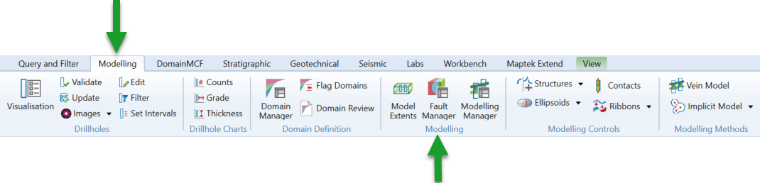
The Fault Manager panel appears.
Important! First of all, a major fault surface must be defined in the Chronology tree that cannot be truncated against any other fault surfaces. The first item in the Chronology (whether outside of or within fault network) should be a major fault surface.
-
Select a Fault group name from the drop-down list if there are existing models. However, you can create a new fault group, make a copy of, or rename the existing fault groups.

Create a new fault group 
Make a copy of the selected fault group 
Rename the selected fault group 
Delete the selected fault group - Limits
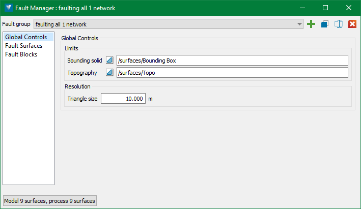
- Define the Bounding solid for the modelling region (mandatory).
The Bounding solid defines the extent limits of the modelling region. All the fault surfaces in the fault group will be limited to the bounding solid, so it is important to ensure the solid covers the volume to be established. -
Define the Topography surface for the modelling region (optional). If a topographic surface is supplied, then the final output fault surfaces and fault block solids will be clipped to the provided topography.
- Define the Bounding solid for the modelling region (mandatory).
- Resolution
The Triangle size defines the global maximum triangle size used in any implicit modelling derived models. The default is set to 5m, but careful consideration to an appropriate triangle size for each model is recommended, as smaller triangle sizes increase smoothness and accuracy of the implicit modelled surfaces relative to input data, but also increase the processing time and file size. This value can be manually overridden as required for each individual model within the group.
-
-
Add modelling items to the Chronology tree.
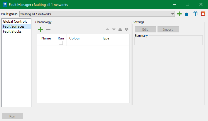
The Fault Surfaces section of the Fault Manager displays a tree of items to include in ‘modelling’ runs. This section is basically where the modelling parameters are defined for each fault surface.
Add a new item to the Chronology tree 
Delete an item from the tree 

Move an item up or down in the tree 

Move an item top or bottom of the tree Note: The order of items in the Chronology tree controls how each entity is combined to create the overall Fault Model. The Fault Manager applies boolean operations in the order of age, where the youngest entity is at the top of the Chronology tree and the oldest is at the bottom.
Adding items
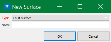
When adding a new item to the Chronology tree, the New Surface panel appears.
-
Select from the Type drop-down list the type of model to be added to the Chronology. These are the surface types available to model:
-
Fault surface - Create an implicit fault surface from CAD and Structural data.
-
Fault network - A group of fault surfaces with the ability to define relationships between each fault within the network.
-
-
Optionally, items in the Chronology tree can be dragged and dropped into other compatible items using the middle-mouse button. For example, a Fault surface can be dragged and dropped into an existing Fault network and a Fault network can be dragged and dropped into another Fault network.
Tip! To add a Fault surface or Fault network into another Fault network, drag and drop the selected item onto the Fault network row with the middle-mouse 'press'.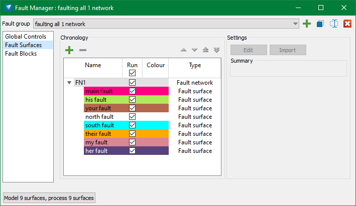
Editing surface modelling parameters
Modelling parameters for each item in the Chronology tree can be defined by selecting the row in the tree and pressing the Edit button on the right of the panel. The Edit button brings up different panels depending on the surface type selected:
-
Fault surface
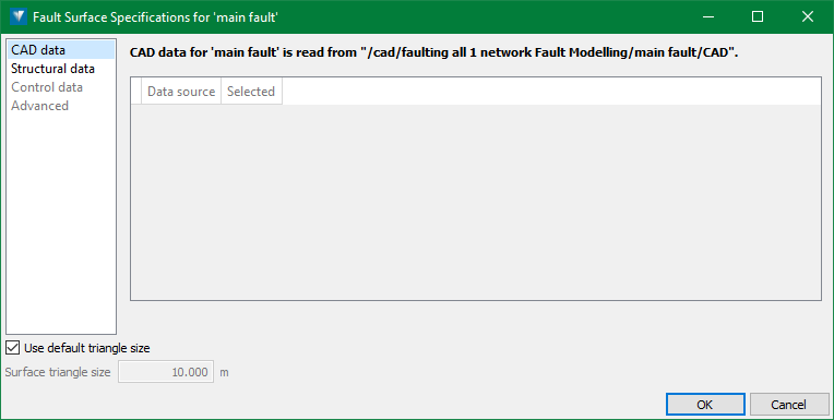
The Fault Surface panel appears.
-
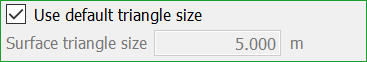
Triangle Size
Use or override the default triangle size inherited from the Fault Group Global Parameters.
-
CAD data
The CAD data is automatically read from the pre-created containers in the CAD container.
-
Structural data
The Structural data is automatically read from the pre-created containers in the CAD container.
For more information about using structural data, refer to Structural Data.
-
Control data
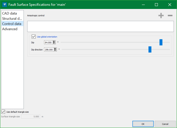
Fault surface models can be constrained and controlled in many ways. Switch to the Control data tab for other methods of controlling the model, described below.
Anisotropic control
Ellipsoids provide localised anisotropic control. Use them to orient the model along a structural trend, or to bridge gaps which may appear in sparse data.
In the Anisotropic control list, specify one or more ellipsoids
 . It is recommended that a few ellipsoids are used initially, adding more later only if required.
 Expand to see instructions on how to create an ellipsoid.
To create an ellipsoid:
-
On the ribbon, navigate to Modelling > Implicit Modelling >
 Ellipsoid.
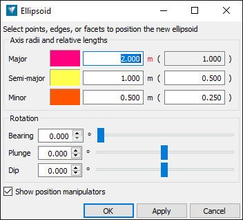
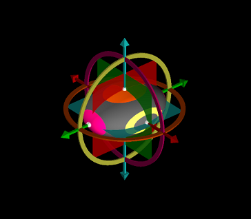
The Ellipsoid panel appears and an ellipsoid appears in the view at the centre of rotation.
-
Configure the ellipsoid by changing values in the panel, or by using the ellipsoid’s dynamic manipulators in the view.
Click and hold the middle mouse button on an ellipsoid manipulator or the ellipsoid itself to change the ellipsoid’s size, shape, or position.
-
Click OK or Apply to create the ellipsoid.
The ellipsoid
is created and saved into the geomodel standard container  .
.
See more detailed information about creating and editing ellipsoids in Ellipsoids.
Use global orientation
Selecting this option allows a global Dip and Dip direction to be used for generating simple and relatively steeply dipping fault surfaces. However, using structural data may generate better results for more complex fault surface.
-
-
Configure advanced options
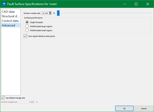
Switch to the Advanced tab to configure advanced options related to modelling performance and evaluation.
-
Domain overlap ratio—Increasing the overlap ratio may provide a tidier result by reducing large artifacts, at the expense of longer modelling time. Even small increments will have a significant effect on modelling time. It is recommended that small changes are made first to compare the results.
-
Surfacing performance—Multithreading is a way of taking advantage of multiple processors to reduce processing times, but due to the modelling algorithm implementation, it may be at the cost of robustness. Choose between the following threading approaches:
-
Single threaded—A single thread is used. This is the most robust method but takes the longest time.
-
Multithreaded large regions—Use multiple threads, dividing the surfacing into large regions that can be processed in parallel.
-
Multithreaded small regions—Use multiple threads, dividing the surfacing into many smaller regions. Potentially the fastest method, but also potentially the least robust, with holes potentially forming in the surface. This method is useful for quickly examining a model.
-
-
Save signed distance data point—Select this checkbox to save the signed distance data points used to create the implicit model. This will include points from supplied data as well as any generated infill points. The points will be saved in the model container. You can inspect the signed distances using the Point Attributes tool. Distances greater than zero are points outside the solid. Distances less than zero are points inside the solid.
-
-
-
Fault network
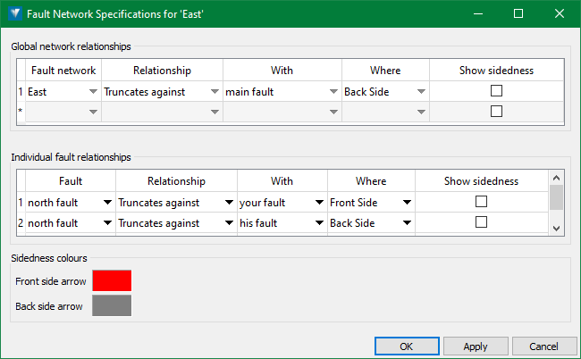
The Fault Network Specifications panel appears, which allows relationships to be defined both at the global level and how each fault surface interacts with others within the network.
Fault surfaces can only be truncated against younger fault surfaces (i.e. surfaces ABOVE the selected surface in the chronology).
-
Global network relationships—Use this option to define relationships that will be applied to all fault surfaces within the network.
Note: For nested fault networks, any child network inherits the Global network relationships of its parent. This is currently not shown on the panel of the child network, but will be added as a read-only item in the grid in a future release.
-
Individual fault relationships—Use this option to define relationships between fault surfaces within the network.
-
Relationships
-
Surface—The surface to which the relationship will be applied.
-
Relationship—The type of relationship to be defined:
-
Truncates against—The selected surface will be booleaned to truncate against the side of the vein defined in the With column.
-
-
With—The relationship surface to be used to apply the relationship to the selected vein.
-
Where—Where to apply the relationship. For example, using the Truncates against relationship allows defining whether the surface will truncate against the hanging wall or footwall of the relationship surface.
-
Show sidedness—Loads both fault surfaces defined by the relationship as temporary objects into the current view and highlights the ‘sidedness’ of each, to help easily determine the desired side to truncate against.
-
-
Importing surface modelling parameters
Select the surface(s) in the Chronology tree and press the Import button on the top right of the panel. This allows settings to be imported to the selected surface(s) from another surface model.
Note: Currently, this option imports all settings from the selected surface(s). This will be made more customisable in future allowing to select desired settings for the import.
Creating models from the Chronology tree
Once the desired settings have been set for each surface in the Chronology tree, the checkbox in the Run column can be selected, which will add the selected surface to the pool of surfaces to be modelled.
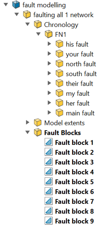
When the Model button is pressed, each surface in the pool will be modelled and any Fault network rules will be applied to Fault surfaces within networks. All outputs for the selected modelling method will be saved into the fault modelling container, following the hierarchy of the Fault Group.
Fault networks will have a container created that will contain the output of all fault surfaces within the network after the network relationships have been applied. These containers can be further expanded to access individual fault surface items.
-
-
Add Chronology modelling outputs to the Fault Blocks processing.
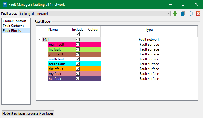
The Fault Blocks section of the Fault Manager displays a tree of items to include in Fault Blocks processing runs. This section can be thought of as adding the outputs from the Chronology modelling runs to a final Fault Blocks.
During this process, boolean operations are applied to each item in the order of age. The order of age is defined with the youngest item being at the top of the Chronology tree and the oldest being at the bottom.
Items can be added to the Fault Blocks using the checkboxes in the Include column.
Note: Chronologymodelling does not need to be run at the same time as being added to the Fault Blocks. The Fault Blocks uses all final (truncated) surfaces from the Chronology Modelling so that modelling for each surface can be finalised before being added to the Fault Blocks.
Important! It is recommended to check that all surfaces added to the Fault Blocks are valid. While the Fault Manager should automatically report surface validity, click here for more information on checking surface validity. Valid surfaces are important as invalid surfaces can greatly affect the processing speed of the boolean operations and the validity of the Fault Blocks outputs.
Some tips for improving surface validity:
- Adjusting the triangle size of the model can resolve the issues.
- Additional CAD data can be used to control the model in certain areas to help resolve the issues (particularly important where bifurcated vein limbs merge).The Fault Manager output from the examples used in this help can be seen in the images below:
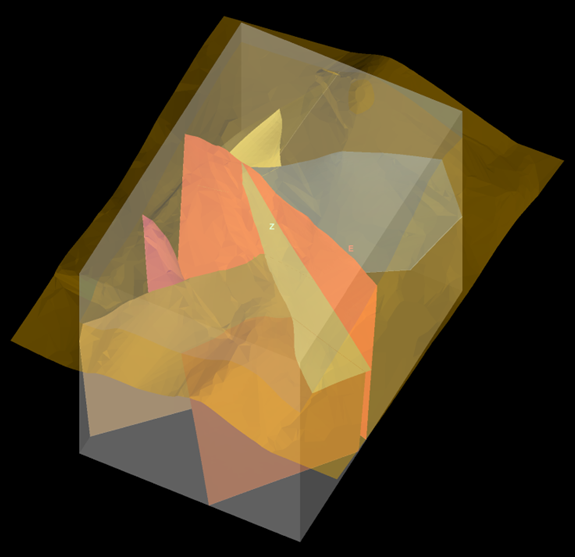
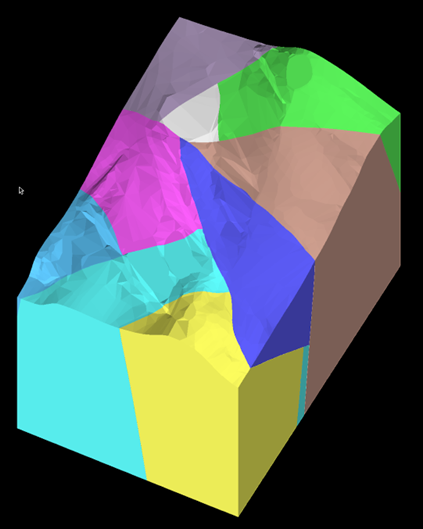
|
Create a Geology Model
|