

 Site Configuration
Site Configuration Options provide comprehensive administrative control over the system's operational, data, and behavioural settings. The key tools include:
-
Site Parameters: Define the modelling behaviours and attributes of zones, stockpiles, and event processing thresholds.
-
Preferences: Configure how site-related information is handled, including coordinate systems, units, metadata synchronisation, and visualisation assets.
-
Material Properties Schema: Manage and review material property schemas from various sources like FMS, geological, and grade control models.
-
Resource Model Explorer: View, import, activate, and manage geological and grade control blocks used in material tracking.
-
Rules Editor: Modify, validate, and automate site-specific business logic through configurable scripting rules.
-
Zone Maintenance: Create, import, and maintain zones with set boundaries and characteristics that influence material flow and analysis.
These tools allow administrators to tailor MaterialMRT to the specific operational, data integration, and compliance requirements of the mining site, ensuring accurate material tracking.
Site Parameters
This page allows you to adjust the attributes of the mine and the behaviour of its materials, as follows:
|
Global |
Cuboid Length and Width: A cuboid is a block used for modelling stockpiles. It is similar to a conventional block-model block, but its height varies in proportion to the quantity of material it represents. To set the base size, enter a value in the Cuboid Length and Width field. Note: Cuboid length and width can only be changed if no materials have yet been modelled in the system. |
|
Typical Material Density |
Typical materials are categorised as non-specific types used as baseline or default materials, such as reject, waste, and re-handled. They serve as general classifications for modelling and operational tracking when specific material properties or detailed classifications are not assigned.
|
|
Zone Category allows administrators and operations supervisors to create categories and assign tags that define a zone's behaviour and purpose. To add a new zone, follow these steps:
To remove a zone category, click |
|
|
Rule |
Rules are scripts that validate and automatically correct data associated with the movement of material. TypeScript is used for developing or modifying rules. To select which rules to enable, use the adjacent checkbox. Users require a role with the Modify Rules permission applied. To save any changes, click |
|
The cuboid stack modeller adjusts the behaviour of material that is added or removed from a stockpile. The settings are as follows: Note: Changing these settings may affect system performance.
|
|
|
Stockpile Boundary Modeller |
The stockpile boundary modeller allows you to adjust the vertical modelling behaviour around a stockpile. The settings are as follows:
|
|
Domain Event Dispatcher |
The domain event dispatcher allows you to set the threshold of the number of events logged before they are dispatched to the system and the lag time before a replay is triggered. The settings are as follows:
To change the values for H, M, and S (hours, minutes, and seconds), you can enter the value directly into each field, or use the |
|
Stockpiling |
Stockpiling allows you to set the age waste dump material reaches before being archived. Select one of the following behaviours:
|
 to add a material, then enter a Material name and Density value for the new material category.
 and
and  buttons to increase or decrease the current value.
Preferences
This page allows administrators to define the technical and operational characteristics of the mine site. Click on a preference category in the side bar to view and edit its settings, then click  to save the changes. Each preference is described in the following table.
|
Site Metadata |
Site metadata identifies the MaterialMRT website instance, and can synchronise schedules with Maptek Evolution Epoch. It includes the following fields:
|
|
CRS and Local |
Control how your terrain coordinate data is mapped by entering the following information:
|
|
Units |
Set standard units for all metrics. Click the drop-down to select the preferred unit. |
|
Stockpile Status |
Use the colour picker to select the default colour for displaying undefined materials in the colour map. |
|
Cesium Default |
Add or remove viewer terrain (assets). Click
|
|
Zone Categories |
Review and manage the zone categories as they relate to their respective roles in the run-of-mine operation. Add tags to modify the behaviour of a category by clicking on New Tag... and selecting one or more of the following:
To remove any tag, click over the 'x' inside its tag. |
|
Enter your language and regional settings in this tab. The following fields apply:
Tip: For each of the above, begin typing a keyword to narrow the search. For example, if you type “US” into the Culture field, matches such as chr-US, en-US appear. You can do the same to find the correct Time Zone. Alternatively, open the entire list by clicking in any of these fields while it is blank. |
|
|
Shift Calendars |
Select the shift system used at the site. Use the drop-down to select a preset shift or create a custom one. Each shift has a start and end time using a 24-hour clock. To set a custom time, select Custom. To enter shifts, click To name the custom shift by its ending day, enable Name Shift After End Day. |
|
Viewer |
Set the amount of padding around the extents around the combined zones when displayed in the viewer. The unpadded extents form a rectangle sized to fit the outermost boundaries of all zones within the terrain. To see the effects more clearly, configure any viewer as follows:
Tip: To learn how to configure a viewer, see Getting Started > In-viewer configuration controls. Example
With Use Zones with padding as Terrain Extent set to 0, the white boundary is set to the limits yellow zone boundaries with no padding.
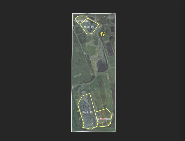
To set padding uniformly, do the following:
Example
The padding between the yellow zone borders and the white extents border. In this example, the padding value is 200 m.
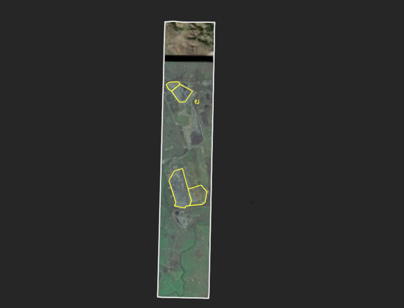
You can also define explicit minimum and maximum x- and y-axis (mine grid) coordinates, as follows:
Example
Note the padding effect (particularly the vertical extents when custom settings are applied:
|
| Built-in Metric Colouring |
Manage the colour schemes of built-in metrics—such as those displayed.
|
 : Zones with this tag are displayed the Zone Maintenance page
 : Zones are visible to all viewers.
 : The Zoom to option can be used by the viewer to set the camera location.
 : Stockpiles with this tag cannot be renamed from the viewer or stockpiles page.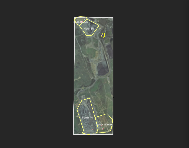
 to select and edit a pre-made colour map.
Material Properties Schema
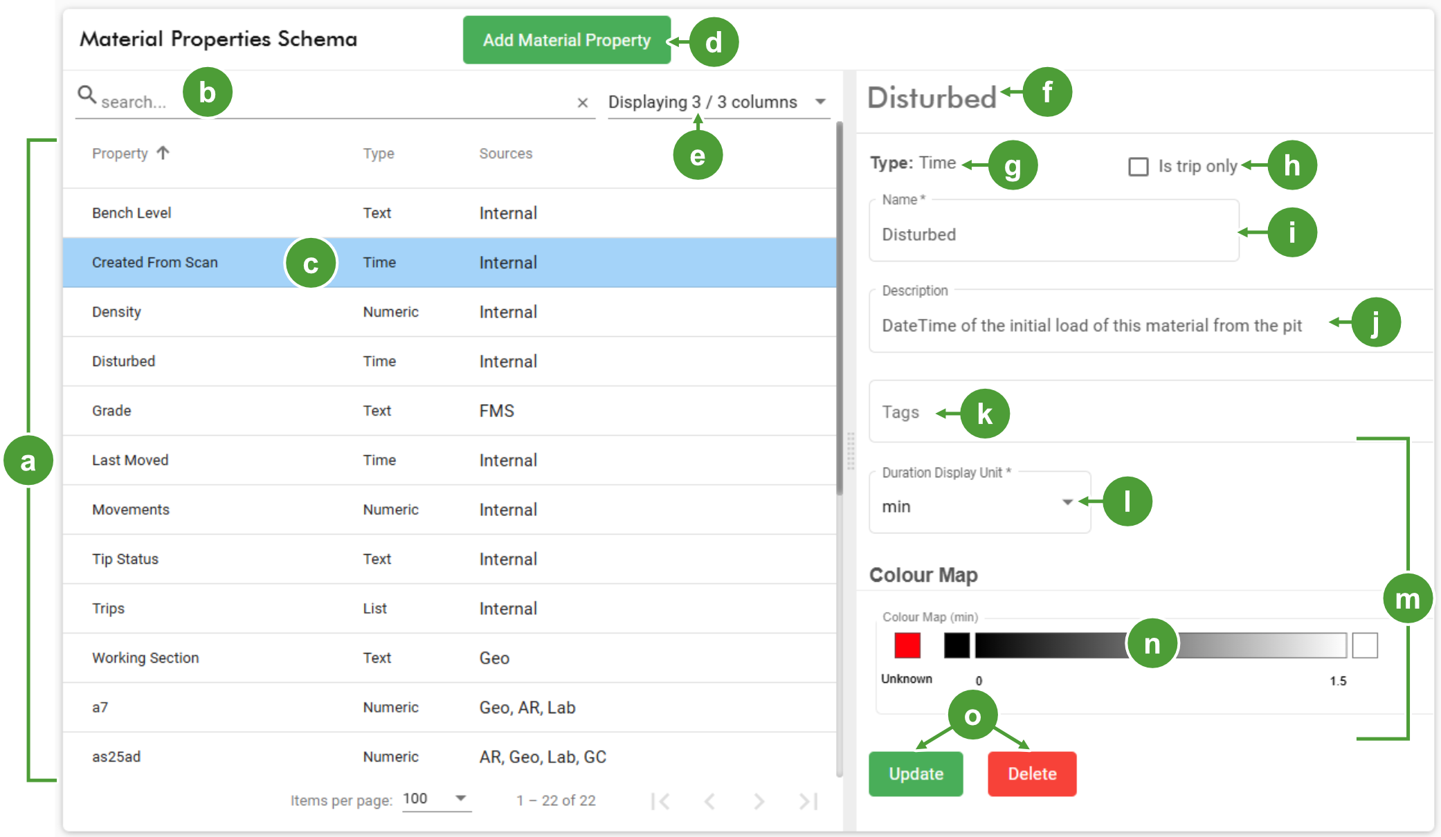
The Material Properties Schema is a management tool for all properties used by MaterialMRT. A table listing the property, along with its type—numeric, text, list, and time—and sources. The table is searchable, allowing a specific property to be found. and the editor in the adjacent panel allows an operator with the Modify Material Schema permission to add, remove, or edit properties.
|
|

|
Properties table |

|
The property name (editable field when adding a property) |

|
Search field for the table |

|
Description of the property’s function |

|
Selected property |

|
Apply a read-only or hidden attribute to the property |

|
Add a material property button |

|
Select a dimensional or dimensionless unit of measure |

|
Display columns drop-down |

|
Material details section ( measures, sources, value ranges, and colour map) |

|
Name of selected property (editor) |

|
Colour map (if applicable) |

|
Property type (a drop-down when adding a property) |

|
Buttons to save or reject applied changes |

|
The property is registered as a trip only if the checkbox is enabled |
Adding a new material property
To add a property, click  to open a blank property editor panel called, New Material Property . Follow these steps to enter the new data:
Note: (*) denotes a mandatory field.
-
Under Type,Select the property type. For more information, see Site Configuration > Property types .
-
Enable Is trip only if the property is not intended to carry through to cuboid stacks, stockpiles, or outflows. The information is only retained in the trip and can be used in downstream reporting systems.
-
Enter the property name into the Name field.
-
Enter a description for the property into the Description field.
-
Click Tags to enable hideValues to make the property read-only, or hidden to make the property invisible to users, if required.
-
Open the Measure drop-down and select the appropriate metric.
-
Open the Display Unit drop-down and select the appropriate unit.
-
Under Sources, click
 to select one from the drop-down list. Repeat this step to add more sources.
 -
Under each source, enter the Source System Key exactly as named from the source. Also select the unit of measure in the Source Unit drop-down.
Note: Different source system keys may have naming variants, such as a7, a-7, or ash7. To correctly map a property to its source system, ensure its key exactly matches the source name.
-
Under Value Ranges, click
 to enter value ranges for Acceptable, Marginal, and Unacceptable. Repeat this step to include additional value ranges as required.
 -
Under Colour Map, click
 to open the Customise Colour Map panel. Add value increments matching the previously set value ranges, then assign colours and visual styles to build your colour map. For more information, see Getting Started > Creating or modifying colour maps.
 -
Click
 to save the property.
Deleting a property
To remove a property from Material Properties Schema, follow these steps:
-
Select the property from the list
-
On the editor pane, scroll down to find and click
 . A confirmation prompt will appear with the following warning: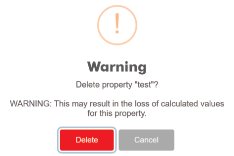
-
Click
to confirm and remove the property.
Modifying a property
To modify an existing property, follow these steps:
-
Select the property from the list.
-
In the property editor, select the attribute to modify or delete
- Enter or edit attribute values as needed.
- Click
 next to an attribute you want to delete.
-
Click
to save your changes.
Property types
The Property types table below, define the attributes and their purpose.
|
Numeric properties |
They are labels with a numeric value that include the following:
|
|
Text |
These are labels or character strings that contain one or more child values. The combined proportions of these child values equate to 100% . |
| Lists |
These are labels or character strings with one or more child values in the form of a simple list of labels. |
|
Time |
This property is a label with an associated Date-Time value. These values are often described in the system as a duration from the Date-Time value to the current time. |
|
Default system |
The following properties are built into MaterialMRT: Trips: A trip lists the trip keys/IDs that are associated with a parcel of material. Note: Once there are more than 5 trips in this list it is emptied as tracking the material this way becomes more speculative. Movements: A movement tracks how many times a parcel of material has been relocated. Example: 1 movement from pit to ROM stockpiles, 2 movements then from ROM stockpile to sink. Disturbed: This is a time stamp for material when it was first loaded from the pit or stockpile. Tip Status: This is associated with the Dump Location Validation typescript rule. It can be any text value defined by the rule. |
Resource Model Explorer
The Resource Model Explorer is a tool that manages grade control and geological block models. Its interactive viewer displays either type of model—colour mapped to their associated properties—over the terrain, allowing additional information to be explored. The adjacent pane includes:
-
an Explore tab with a table for browsing model data,
-
an Import tab for creating new resource models from CSV or ZIP files, and
-
a Manage tab for editing model details and setting models as active or inactive.
This tool helps ensure that material tracking, grade control, and reconciliation workflows remain connected to accurate, up-to-date resource model data, supporting mine planning and operational decision-making.
|
|
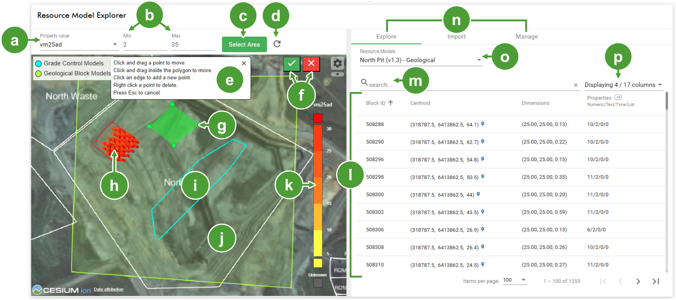
|
|
Property value drop-down |
|
Grade Control Models area (inactive until - Grade Control models are selected) |
|
|
Minimum and maximum filter (geological blocks only) |
|
Geological Block Models area (active selection) |
|
|
Select area tool (create polygon to display geological blocks) |
|
Colour map for the selected property value |
|
|
Apply Min and Max filter and show blocks |
|
Table of blocks and its related data |
|
|
Create polygon tooltip |
|
Search field for the table |
|
|
Save and cancel polygon buttons |
|
Explore (selected) Import, and Mange tabs |
|
|
Completed polygon (before clicking  ) ) |
|
Resource Models drop-down (select a grade control or geological block model) |
|
|
Geological blocks (after clicking ) |

|
Show or hide related information columns |
Viewing blocks and their properties
The viewer displays the following features, depending on the type of block model selected, as follows:
-
Grade control models appear within a cyan border. To display them, open the Resource Models drop-down in the Explore or Import tab and select a model with the -Grade Control suffix. The blocks are colour-mapped to the first listed property type and appear at terrain level, as illustrated.
-
Use the Property value drop-down to select another property to view.
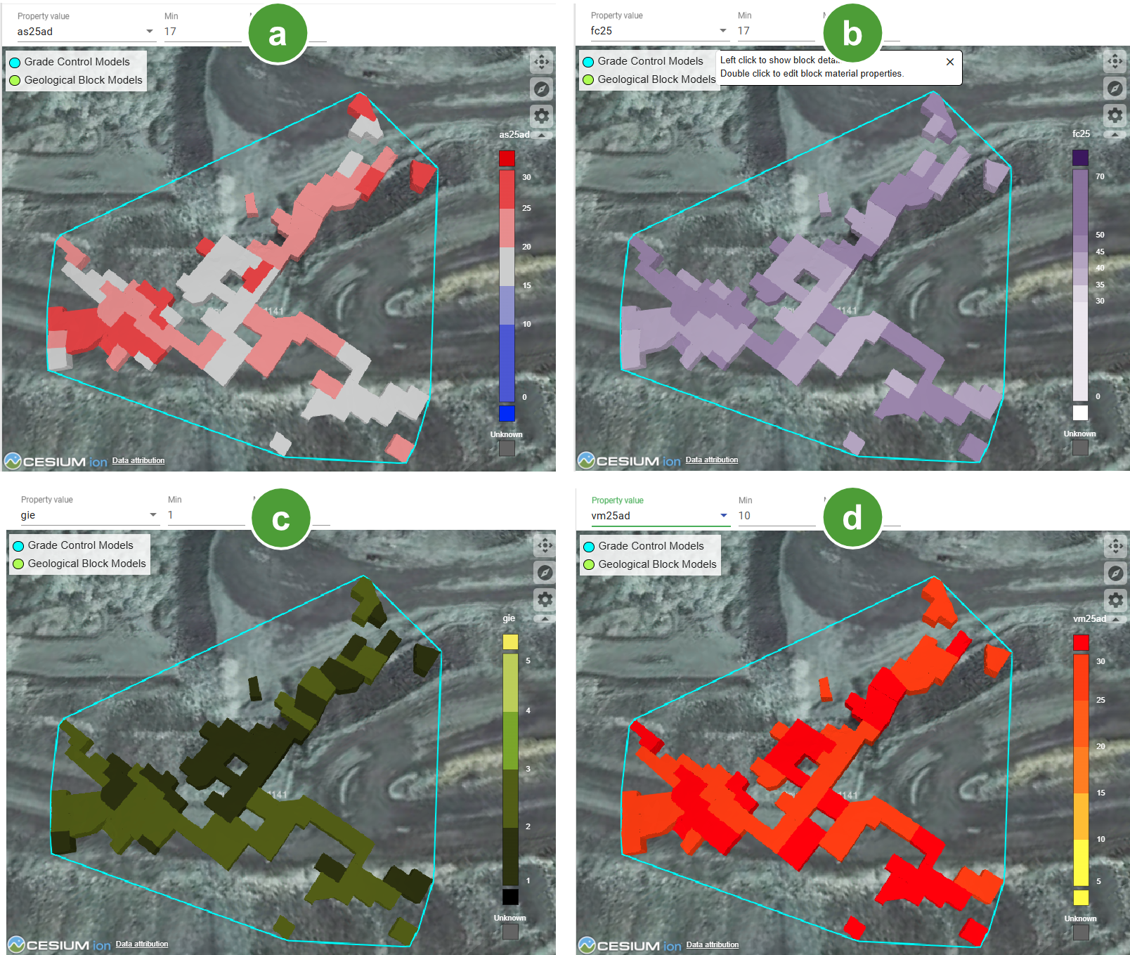
The model shown from (a) to (d) is displayed using colour maps for ash, fixed carbon, gross calorific value, and volatile material content..
-
Click on a block in the viewer to locate it in the Explore tab table.
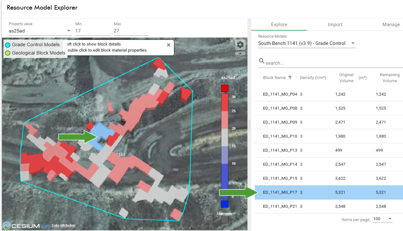
The block turns cyan when selected, causing the corresponding row in the table to be highlighted
-
-
Geological blocks lie within light green boundaries but are not immediately displayed by default, as rendering them requires significant computing resources. When shown, they appear as stacked blocks beneath the terrain, as illustrated below. Geological blocks follow the colour scheme of the selected property.
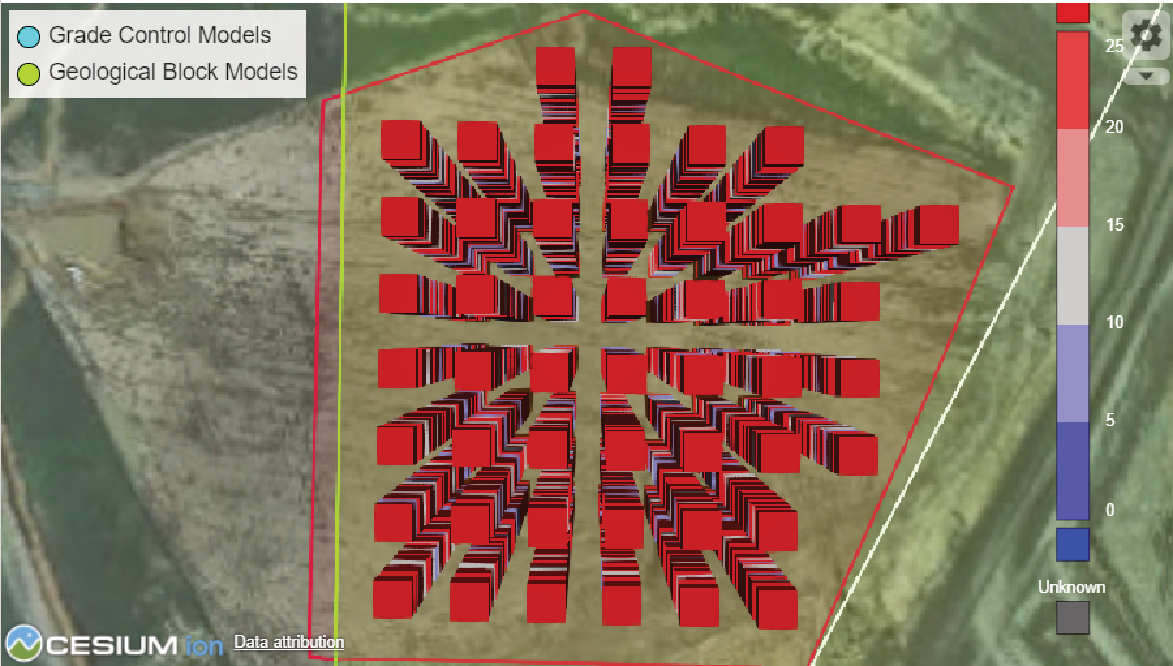
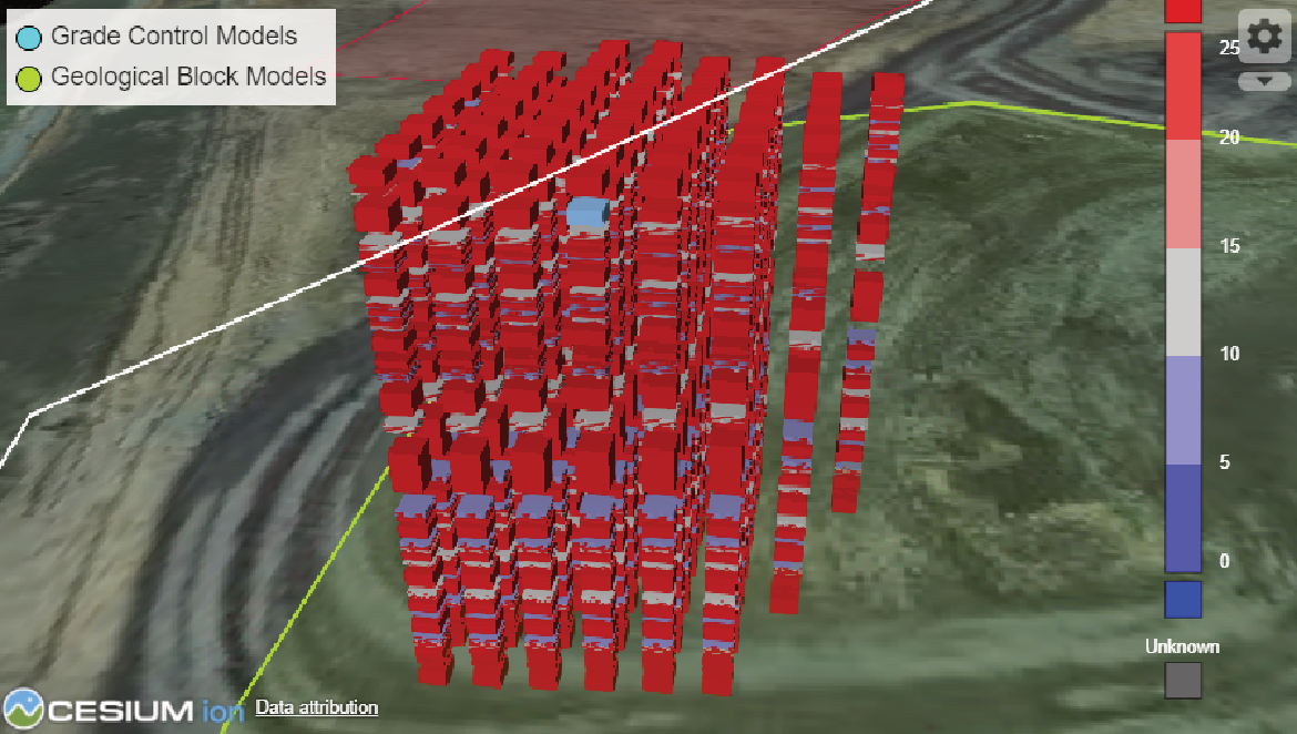
Geological blocks seen from above and with the camera positioned for an orthographic perspective to reveal the underling blocks
To display geological blocks, follow these steps:
-
Open the Resource Models drop-down in the Explore or Import tab, and select a model with the - Geological suffix. The area within green boundary in the viewer becomes translucent green, indicating geological model survey zone.
-
Click
 , then create a polygon following the tooltip instructions in the viewer.
 -
Click
to display the geological blocks. -
To view a an alternative property, click the Property value drop-down and select another from the list.
-
Apply Min and Max filters—values outside of Min and Max are filtered out—then click
 to update the view.
 -
Click on a block to highlight it in the viewer and in the table.
-
-
Using the Explore tab
The Explore tab contains a table listing all grade control or geological blocks from the selected model. Each block attribute—such as the block name, density and other values—is displayed in a separate column, which can be added or removed as required. A search bar allows you to filter table across all visible columns.
-
Select or filter out columns. The drop-down will indicate how many are active out of the total available.

-
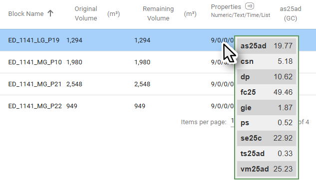
In the Properties column hover over the property types (Numeric/Text/Time/List) summary to display a tooltip of the properties contained and their quantities.
Importing grade control and geological blocks
The Import tab has tools to enable you to import geological or grade control blocks. Geological blocks are contained within CSV or ZIP files. Grade control files require a CSV file with accompanying DXF or OBJ blocks, and the filenames of both must be identical.
To import grade control or geological block models, follow these steps:
-
Click
 to open its form.
 -
Enter the following information:
-
In Model Name, enter a name for the model.
-
In Type , select Grade Control, Geological, or Property Table.
-
In Owner, enter your name.
-
In Version, enter the version number.
-
In Priority, enter a number
-
Enable Is Active to add the model to the Resource Models list, otherwise it will only appear in the Manage tab until activated.
-
Click
 to save the empty resource model.
-
-
Use the drop zone to add the required files to the empty resource model. Click inside to open a file explorer, or drag files directly into the zone.
Files added to the drop zone appear as tiles labelled with their file name.
-
Click
 to remove unwanted files in the drop zone.
 -
Click
 to clear all files from the drop zone.
-
-
Click
 to import the selected files into the new resource model.
Managing block models
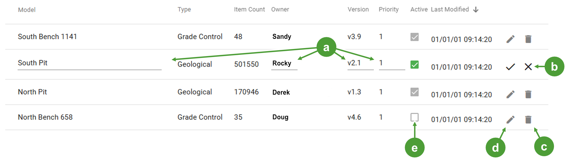
The Manage tab lists all models in the table. Its columns include, Model (name), Type, Item Count (number of blocks), Owner, Version, and Priority. Each row includes controls for editing general information such as the model name, owner, and version number. Block characteristics cannot be changed. To enter edit mode, click or in its row . Other rows remain locked until you exit edit mode by clicking  or
or  . To Delete a model, click
  , then click to confirm.
|
|
|
|
In edit mode, editable fields are underlined |
|
Delete model |
|
|
Save and Cancel edit-mode buttons |
|
Enable edit mode |
|
|
Inactive model |
Note: Inactive models are excluded from queries—for example, TypeScript rules—that specify active models.
Rules Editor
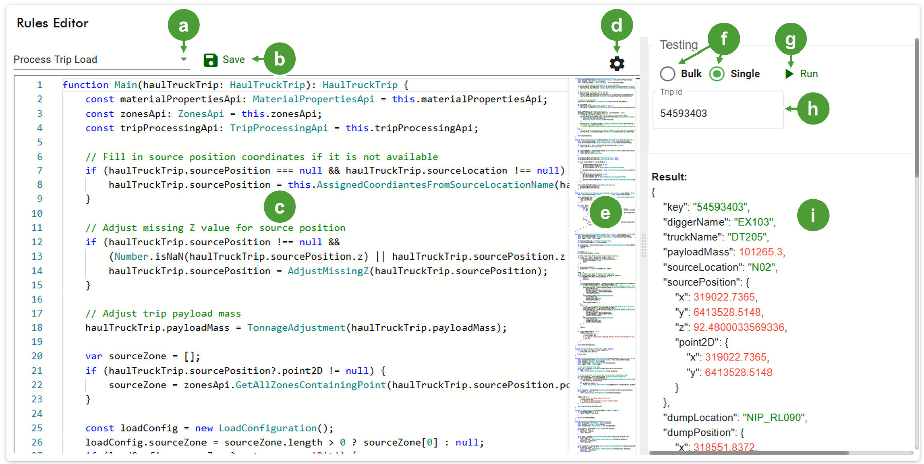
MaterialMRT runs inbuilt and custom automation scripts that query, evaluate, and validate tracking workflows. The script editor allows administrators and power users to create, manage and validate TypeScripts—known as rules—and to run them under test conditions to ensure data integrity.
|
|
|
|
TypeScript Rule selector |
|
Radio buttons to select bulk or single-trip testing |
|
|
Save changes to edited TypeScript |
|
Run button to test the script |
|
|
Editor pane |
|
Trip ID for a single trip or Date and Time Picker for bulk testing |
|
|
Editor theme settings |
|
Output returned by the test script |
|
|
Minimap |
Editing TypeScript rules in MaterialMRT
To edit a rule in MaterialMRT, select it in from the drop-down list above the editor window. By default, the Trip Validation and Payload Auto Correction TypeScripts are available and mandatory. To display other scripts, enable each rule by selecting its checkbox in Site Parameters > Rule. Below are examples of rules that are used by MaterialMRT:
|
Trip Validation |
The rule is run when viewing trips on the Trip Editor page. This script performs the following functions:
If trips return error or warning validation results, the applicable column is coloured in red or orange respectively. |
|
Payload Auto Correction |
This script applies this rule to all selected trips in the trip editor. It automatically corrects the payload mass to the expected payload mass of the named truck. If the truck name does not match, an error is returned to indicate the payload mass can’t be corrected automatically. |
|
Trip Auto Correction |
This rule is run every time a truck trip is processed. It is able to modify any value available on the HaulTruckTrip model used by the rule. It also has access to various application program interface (API) methods to query related zones, stockpiles, and block models. |
|
Resource Model |
This rule is run by the engine every time a truck trip is processed. This rule is used when selecting a grade control or geological model block to associate with a load event of a truck. |
|
Dump Location |
This rule is associated with the Tip Status material property. It is run every time a trip is processed and determines if the material was deposited in the correct location. |
| Process Trip Load | To ensure accurate reporting of haul truck trips, this script processes data from a haul truck to determine the source, position, and elevation. The payload mass will be adjusted if the value is zero or negative and assigned a default value. Material properties will also be assigned based on whether the source is within an extraction zone or at a stockpile. |
| Process Trip Dump | This script processes a haul truck's dumping event by determining the dump location, adjusting missing data, and updating the trip's payload information accordingly. It uses similar adjustments to the Process Trip Load rule. |
Testing TypeScripts
Testing a TypeScript allows you to verify that an automation runs correctly and does not introduce errors into the system, using either a single instance or bulk data samples. Testing any modified script is mandatory—if you click  before testing, a panel appears stating “Code must be tested and pass before saving”. In this case, click
  to close the panel, then follow these steps:
-
Under Testing, select either Bulk or Single using the radio buttons.
-
If bulk testing, use the Date Time Picker to select a suitable time interval, or for a single trip, under Trip ID enter a valid number.
-
Start the test by clicking
 , then check the results and debug any errors.
 -
When the script is successfully validated, click
to update it.
Zone Maintenance
A zone is a defined spatial area—typically represented as a polygon—used to specify locations within a run-of-mine operation. Zones may encompass pits, stockpiles, or other areas where materials are extracted, stored, or processed. They play an important role in organising operational data, supporting reporting, and enabling accurate material tracking across different locations.
Zones consist of polygons and solids that form an area mapped to a specific location. Polygons are displayed as 2D planes and are derived from kml, json, or dxf files. Solids are 3D triangulations from dxf and OBJfiles, and users can report on material contained within the solid itself.
Zone Maintenance allows the user to manage zone polygons and solids and import updated versions of both. The interactive viewer displays zones or solids enabling them to be easily identified or selected for editing, exporting, or removal from the system.
Managing Polygons
The Manage tab contains a searchable table that lists each zone by its name and category, supporting multiple functions. The search bar filters keywords in all visible columns to minimise unwanted data.
-
Click on a zone in the table or the viewer to select it. This also populates the editor pane with its details. Selecting a zone in the table also centres it in the viewer to help identify it in the terrain.
-
Use the editor to change information by typing directly into its text fields. You can also change the zone’s category using the drop-down list. Updated polygons can be added through the drop zone.
-
Add new zones using the polygon tool and manually entering the required values.
 Click to view instructions for creating a zone.
To create a new zone, follow these steps:
-
From the manage tab, click
 to open a blank form in the zone editor.
 -
Enter the zone name, select its category from the drop-down list, and enter the required values for each parameter field.
Note: Certain parameters—aside from Name and Category—only apply to specific zone categories.
Zone Name
A unique or site-derived name given to a zone.
Category
Open the Category drop-down to make a selection. A category defines the purpose of that zone. Available categories are derived from those created in the Zone Category section as explained in Site Configuration > Site Parameters.
Capacity
Enter the tonnage of the stockpile.
File units
Open the drop-down to select an alternate file unit to apply.
Conveyor speed Enter a value for the rate at which the conveyor belt moves, if applicable.
Flow rate Enter a value that a given mass of material moves past a set point every second, if applicable. Distance to analyser Enter a value for the distance the material has to travel to arrive at the analyser, if applicable. Distance to lab sampler Enter a value for the distance the material has to travel to arrive at the lab sampler, if applicable.
Prefer ground scan
z-coordinatesEnable the checkbox to use terrain scan elevation over the imported scan, where possible.
-
Click
 (add polygon) and begin plotting the area in the viewer. Alternatively, import a polygon by dropping a
 KML,JSON, orDXFfile into the drop zone. -
Click
 to save the zone. The new zone will be displayed in the viewer.
 Tip: To adjust or reposition a polygon you created, select it, then click
 . Edit the polygon, then click to save your changes. To exit edit mode without saving any changes, click
  .
. -
Click
 beneath the zone editor to finalise the newly created zone and add it to the Zones list.
 Tip: If the new zone is not displayed in the list and the viewer, refresh the browser window.
-
- Delete obsolete zones. Select the unwanted zone from the table, then click . A warning dialog will appear to confirm your request.
Importing zones
The Import tab enables you to import zones in bulk. You can select any combination of KML, JSON, or DXF files and drop them directly into the drop zone, or click on it to navigate to your source files. The steps involved are as follows:
-
From the File Units drop-down, select the preferred unit.
-
Enable the Prefer terrain scan z-coordinates checkbox to override the zone elevation data in the import files, if included.
-
Choose the following ways to import a file (supported file types are KML, JSON, and DXF):
-
Click in the drop zone to open a file explorer, or simply drag available files into it.
Uploaded files will appear in the drop zone as labelled tiles.
-
Click
to remove any tile in the drop zone, including from the import table. -
Click
to remove all files from the drop zone and table.
-
-
Use the check boxes to select which zones to include, all zones are selected by default.
-
In the table, update the zone name, if required and
-
Under Category, allocate a zone category using the drop-down. All zones must have a zone category allocated to it.
-
Click
 to complete the import.
To view the newly imported files, select the Manage tab.
Exporting all Zones
You can export all zones to a file in the units of measure you have set, click the  button and select the preferred file format (KML, JSON, or DXF) from the drop-down. The file will be saved in your default download directory as
 <Site Code>.zones.xxx.
The following is exported as a JSON file DEMO.zones.json
where:
-
DEMOis the site code. -
.zonesidentifies this file as zone data. -
.json is the output format selected by the user.
Managing Solids
Zone solids are 3D volume models—typically DXF or OBJ triangulated solids—that define enclosed spaces in three dimensions. They provide volumetric boundaries for pits, stockpiles, dump areas, and similar locations, enabling spatial analyses such as volume, mass, and material distribution within a closed 3D region.
The Manage Solids tab enables supervisor-level operators to maintain zone solids. They are listed in a table that includes each solids’ name and category. The adjacent editor allows you to change the name—but not the category—as needed, and the viewer provides visual context within the terrain.
-
Click on a solid in the table or the viewer to select it. This also populates the editor pane with its details. Selecting a solid in the table also centres it in the viewer to help identify it in the terrain.
-
Use the editor to change the name of an existing solid or when adding a new one. You can also change the zone’s category using the drop-down list. Updated polygons can be added through the drop zone.
Importing Solids
To import a zone, follow these steps:
-
Click
to clear the details section. -
Enter a unique name in the Name field.
-
Select Report Solids from the Category field.
Note: To be a reportable solid, ensure that the Reportable tag has been assigned to that category, see Site Configuration > Zone Category.
-
Select a valid
DXForOBJfile via the drop zone. When prompted, select the appropriate file unit then click. -
Click the
button to add the solid to the table.
Importing zones
The Import tab enables you to import zones in bulk. You can select any combination of KML, JSON, or DXF files and drop them directly into the drop zone, or click on it to navigate to your source files. The steps involved are as follows:
-
From the File Units drop-down, select the preferred unit.
-
Enable the Prefer terrain scan z-coordinates checkbox to override the zone elevation data in the import files, if included.
-
Choose the following ways to import a file (supported file types are KML, JSON, and DXF):
-
Click in the drop zone to open a file explorer, or simply drag available files into it.
Uploaded files will appear in the drop zone as labelled tiles.
-
Click
to remove any tile in the drop zone, including from the import table. -
Click
to remove all files from the drop zone and table.
-
-
Use the check boxes to select which zones to include, by default, all zones will be selected.
Tip: If you have many zones in your list, consider using Search Zones to filter the list.
-
In the Category column, allocate a zone category using the drop-down. All zones must have a zone category allocated to it.
-
In the Capacity column, enter the capacity (tonnage) expected to be in each zone.
-
Click
to complete the import.To view the newly imported files, select the Manage tab.
