Throw
Select this option to convert fault strings into fault horizons where the required throw is specified by the W- tag of the string points.
There are two modes this option offers:
- If Model throws with dips option is selected, each of the horizon surfaces is faulted along the line of the string by an amount specified in the W-tag. Refer to the Load Fault Strings option for information on how this is set up.
- If Model throws with dips option is not selected, in addition to the W-tag, the names of each point in the throw string specify the dip of the fault in degrees. This information is used to create fault planes (triangulations) which are used to fault the horizon surfaces allowing both thrust and overthrown faults to be modelled.

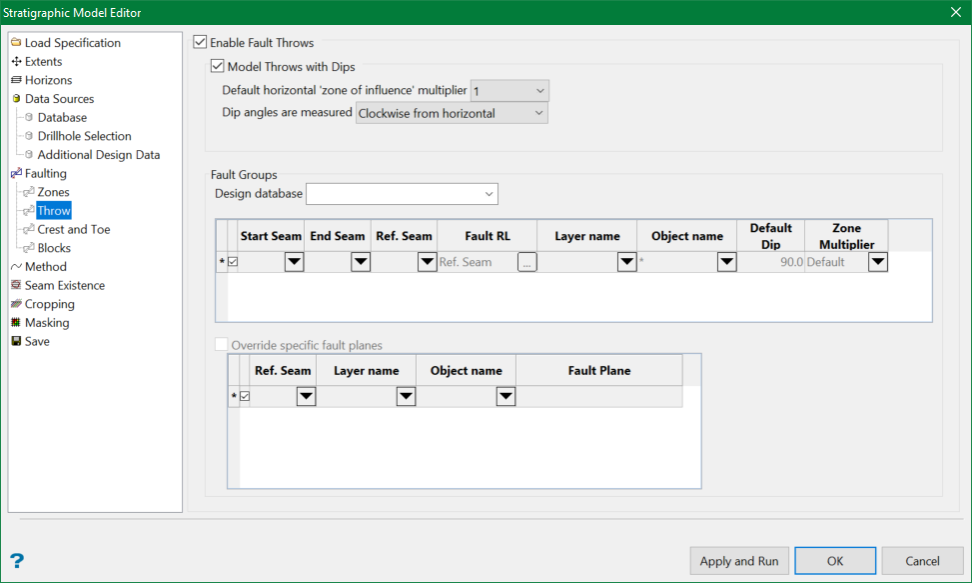
Enable Fault Throws
You will need to nominate the design database that contains the strings of interest as well as the horizon(s) that you want to fault. A layer name and object identifier relevant to each horizon will also need to be chosen.
Model Throws with dips
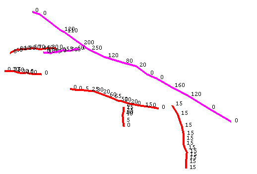
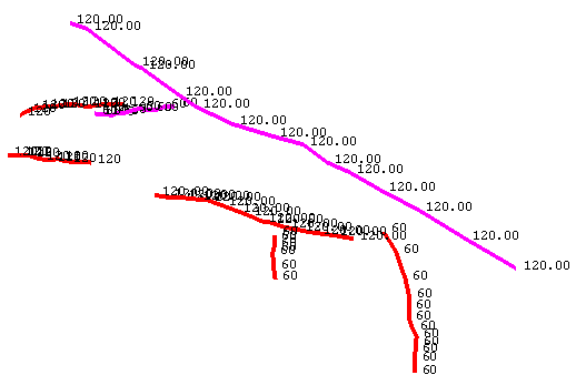
Allows for more complicated faulting of any or all horizons using uniquely named string objects or triangulation surfaces as input. W tag values define throw, whereas point names define dip in degrees.

W tag values define throw

Point names define dip
In lieu of grids, the output is faulted.srt and .sft triangulation surfaces.
Default horizontal zone of influence multiplier
Note: If Fault Blocks are enabled, this option is no longer valid and thus disabled.
Select a factor of how wide the faulted section of a throw string is across a grid extent. The selected factor is applied to the actual throw value. Start with 0 or 1.
A horizontal zone of influence needs to be specified for the throw faulting. The number used is dependent on the throw, large throws require a much larger horizontal zone of influence. Small throws require a small zone of influence.
When a combination of both types of fault exists (i.e., small scale and large scale) the zone of influence becomes important in creating a good representation of the faulting. Also, the zone of influence is influenced by the proximity of the fault to a drillhole, as the throw will move the surfaces away from the borehole intercepts.
Dip angles are measured
Dip angles are measured either clockwise or anti-clockwise from horizontal. When looking along a string from the first point in the string sequence to the last:
-
Clockwise from horizontal results in a dip value of 50 dipping down into the ground to the right at an angle of 50°.
-
Anti-clockwise from horizontal results in a dip value of 50 dipping up into the air to the right at an angle of 50°.
Fault Groups
Design database
Select a Design database which contains fault strings with appropriate RL tag, W tag and point name values.
Start Seam / End Seam / Reference Seam
This defines a range of seams over which the specified fault has an effect. The start seam is the upper limit and the end seam is the lower limit.
The reference seam is a seam within the group to which the specified fault string best relates. The fault string for a specific group will be first registered on to the reference surface before it is projected at the dip angle to create the fault plane.
The seam values can accept the following wildcards:
-
The Start seam can be ‘*’ to indicate the uppermost seam.
-
If the Start seam is ‘*’ the End seam can be ‘*’ to indicate the lowermost seam.
-
If the Start seam is ‘*’ the End seam can be unspecified to indicate the lowermost seam.
-
If the Start seam is NOT ‘*’ the End seam can be unspecified to indicate it is the SAME as the Start seam.
-
If the Start and End seams are the same then the Reference seam can be unspecified.
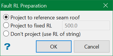
Fault RL
This allows to choose where to project the pit level (RL) fault strings. There are three ways to do that:
-
Project to reference seam roof: Use the roof value of the reference seam.
-
Project to fixed RL : Enter a fixed value of the RL
-
Don't project: Use the existing RL of the string.

Layer name
Select the layer that contains the fault strings.
Object name
Select object name. Wildcards are acceptable.
Default Dip
You have the option of specifying the dip of each fault plane in one of two ways:
-
In the point name (eg. 60.0) for greater granularity along the length of the fault;
-
Using a single value to be applied along the full length of the fault.
Zone Multiplier
This option allows to override the default zone multiplier specified in the Default horizontal 'zone of influence' multiplier option above.
Note: If Fault Blocks are also specified, this option is not required and thus disabled.
Override specific fault planes
Select this option to choose an existing Fault Plane triangulation, which will override specific design data. In the figure below, FAULT_7_OVERRIDE_curvy.00t is used instead of the FAULT_7 object in the FAULT_7 layer for the LOWER seam and any horizons associated with the LOWER seam in the first grid on the Throw pane.

Reference Seam
Select the group to which the specified fault strings best relates.
Layer name
Select the layer that contains the fault strings.
Object name
Select object name. This will be the specific fault string.
Fault Plane
This is the file path to the triangulation that is to be used to override the plane.
Related topics
-
Data Source(s)
-
Faulting

