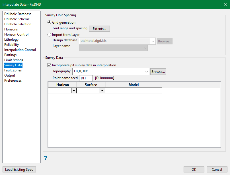
Survey Data
If required, in-pit survey data can be used to control interpolated surfaces. In-pit surveys typically contain thousands of points. This is much more data than is generally found in a drillhole dataset. Therefore survey information can easily overpower drillhole data.
Note: Anomalous survey values may produce incorrect models. Ensure the survey measurements are performed with the same degree of accuracy as the drillhole measurements.
Options in the Survey Data subpanel will limit the survey data to more manageable proportions. The values are modelled on a grid or layer basis, and then dummy holes are created at the grid nodes or from points specified on the layer, which incorporate the surveys available at that location. As well as limiting the data to sensible proportions, this method also allows interpolation of thickness between surveys as well as absolute position.
Survey Hole Spacing
Grid generation
Grid range and spacing
Click Extents to access the Survey Hole Grid Spacing and Model Extents panel. The Extents panel must be completed before Survey Data options are available. There are several ways to define model extents.
Manually enter values for Minimum easting, Maximum easting, Minimum northing, Maximum northing, and Boundary margin.
Click Digitise Range to interactively select the extents visually in Vulcan.
Click Auto-Calculate from Database to respect the extents of the drillhole database selected in the Drillhole Database subpanel.
Enter a Survey hole spacing to define the grid size used to create dummy holes.
Click Import Settings to use values from a pre-existing specification file.
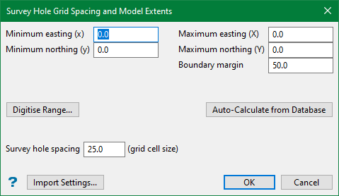
Note: The extents and grid cell size do not need to correspond to the surfaces being used to define the survey pickups. Extents on the Survey Hole Grid Spacing and Model Extents panel are only used to define the areal extent and frequency of the dummy drillhole locations used in this option.
Do not specify the entire grid modelling extent in the Survey hole Grid Spacing and Model Extents panel. This may result in loading a large amount of data and would take a long time to run.
Click OK when all parameters are set.
Import from layer
In addition to defining grid of points, we may alternatively locate a point on the triangulation in case of small surfaces or if needed only for one area (i.e. close to a mine highwall) and generate dummy drillholes from the points specified on a layer.
Select the Design database and choose the Layer that need to be considered importing.
Incorporate pit survey data in interpolation
Select this check box to include pit survey data.
Grid or triangulation surfaces must exist for each set of surveys. The triangulations cannot contain invalid edge effects.
Note: Grid Calc > Create Surface can be used to create Model surfaces from survey pickup data. These surfaces may be stored anywhere on the local machine or network.
Topography
A Topography surface is required. This surface may exist anywhere on the network.
Point name seed
To avoid naming conflicts, each dummy hole created is assigned a name from the entered Point name seed. The entered value can contain up to two alphanumeric characters. The default value is DH.
Dummy holes are created wherever an intersection of the nodes specified in the Survey Hole Grid Spacing and Model Extents panel and at least one of the models chosen in Survey Data occurs. All missing horizons are interpolated at full interpolated thickness in each dummy hole. No existing horizons are forced to zero thickness.
Related topics
- Overview
- Drillhole Database
- Drillhole Scheme
- Drillhole Selection
- Horizons
- Horizon Control
- Lithology
- Reliability
- Interpolation Control
- Partings
- Limit Strings
- Survey Data
- Fault Zones
- Output
- Preferences

