Object
The following table describes the tools in the Object section of the Edit tab.
| Tool | Description | ||
| Join and Close | Used to connect across gaps in lines, to merge common boundaries between different surfaces and cap open ends of surfaces. | ||
| Explode |
|
||
| Fill | Used to fill a polygon object with a solid colour. | ||
| Unfill | Used to remove solid fill from a polygon object. | ||
| Simplify Line | Removes excess points while retaining the shape of a line. | ||
| Subdivide Edge | Inserts points along a line at equal intervals. | ||
| Point Z from Attribute | Displays a selected attribute as height (point z). | ||
| Snap Points | Used to slightly move points (that are close together) to the same point. | ||
| Script | Used to write Java scripts for analysis of point data. |
Join and Close
Lines
-
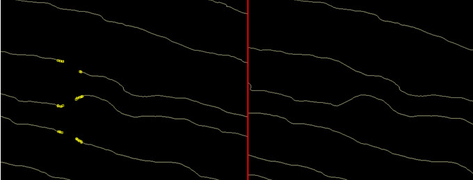
Select points around the gap(s) to be joined. The closest end points of the selected points will be joined together.
-
Go to Edit > Object > Join and Close.
If the end points were not correctly joined, select the end points to connect using the point selection mode and run the option again.
The following example shows contours with removed edges. After the close lines option is run on the point selection, the edges are reconnected.
Surfaces
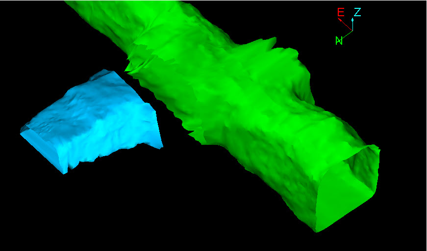
-
Select points around the region to be merged or capped, otherwise select the entire surface(s) to carry out all steps together, producing a single closed object . Create > Surface > Loop triangulation can be used with this function to complete the merging process.
-
Select Edit > Object > Join and Close.
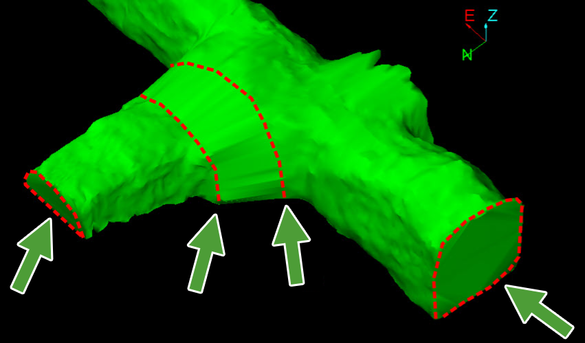
The following example combines with the function at Create > Surface > Loop triangulation to merge and cap three separate hollow surfaces.
Two open surfaces selected (representing sections of a mine tunnel) with a gap between the opening to be joined .
Create > Surface > Loop triangulation creates a joining piece (coloured orange in this example) between the first two surfaces. There are three separate surfaces now, in contact along two common boundaries.
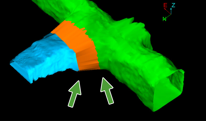
The function firstly identifies where the three surfaces are in contact and merges them into one surface.
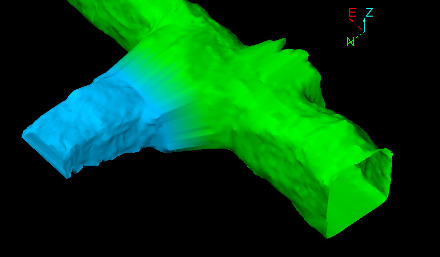
The function continues by capping the ends of the selected surfaces. The result is a single closed solid surface.
The original surfaces were merged along common boundaries and the open ends capped.
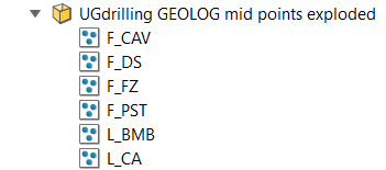
Explode
By Geometry
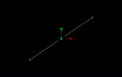
The Explode by Geometry option breaks apart disjoint components of edge networks and triangulations into separate objects.
The object below, on the left consists of two arrows. Once exploded, each arrow is a single object.
To break the object apart into separate objects:
-
Select the object to be exploded.
-
Go to Edit > Object > Explode > By Geometry. The action is carried out immediately on the object.
A container is created with the multiple objects stored inside.
By Attribute
The Explode by Attribute option breaks apart single objects (points) into multiple objects.
To explode by attribute:
-
Select an object.
-
Go to Edit > Object > Explode > By Attribute.
-
A panel will open allowing you to select an attribute. Press OK or Apply to continue. Press Cancel to quit the process.
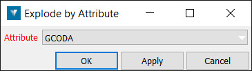
A container is created with the multiple objects stored inside.
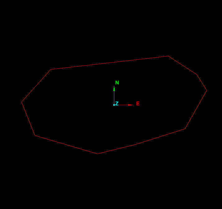
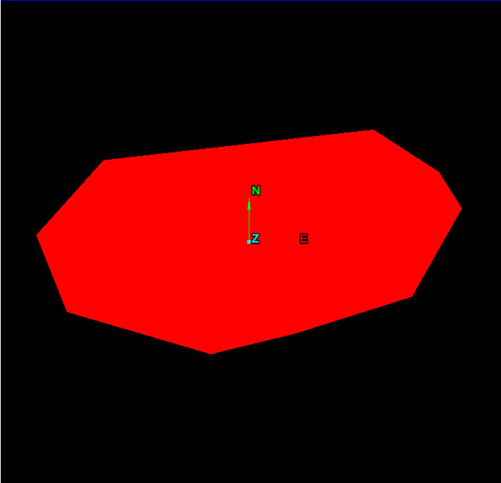
Fill
To fill a polygon with a solid colour:
-
Select the object(s).
-
Go to Edit > Object > Fill or right-click and choose Edit > Fill from the context menu and the polygon will be filled with a solid colour corresponding to the colour currently on the colour palette.
Unfill
Edit > Object > Unfill allows the selected polygon object to be reverted to an unfilled object.
To unfill an object:
-
Select the object(s).
-
Choose Edit > Object > Unfill or right-click and choose Edit > Unfill from the context menu.
Simplify Line
To use the Simplify Line tool:
-
Go to Edit > Object > Simplify line. This will open a new panel.
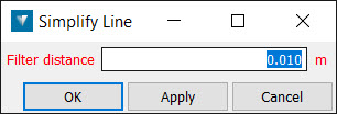
-
Enter a Filter distance. This specifies a maximum distance deviation from the line for which points are retained. As the distance gets smaller, more points are retained and fewer are removed from the line.
Simplified objects can be recovered using the Undo option.
Subdivide Edge
To use the Subdivide Edge tool:
-
Go to Edit > Object > Subdivide Edge. A new panel will open.
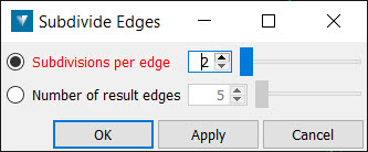
-
Choose one of the following options:
-
Subdivisions per edge— Choose this option if you want to specify the number of equal subdivisions to split the selected edges in to. An edge is a line segment, and the connection between two points. A subdivision of 2 will insert one point midway along each edge in the selection. A single edge within a line can be selected using edge selection mode.
-
Number of result edges — Choose this option if you want to specify new points on the line. For example setting the option to 2 would make a point half way at each segment.
-
-
Click OK or Apply to accept the subdivision
Objects can be recovered using the Undo option.
Point Z from Attribute
The Point Z from Attribute tool is used to display a selected attribute as height. This may be useful for visualising the selected attribute. One example usage would be setting the height of contours imported from Shapefiles which have a height property.
To use the tool:
-
Go to Edit > Object > Point Z from Attribute. This will open a new panel.
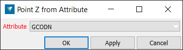
-
Select the objects.
-
Select the Attribute to be displayed as height from the Attribute drop-down list.
-
Select OK. The selected attribute is displayed in the View window as height.
Snap Points
Points can be very close but not on the same point as a result of:
-
Using the Extend to face tool (from the triangulation context menu) on fitted planes. Numerical rounding means the points are very close but not exactly on the same point.
-
Importing data from other software packages. This data can have points that are close, but are meant to be on the same point.
-
On the Edit ribbon tab navigate to the Object group and select Snap Points.
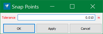
-
Select the two points to be snapped.
-
Enter the Tolerance. This defines the maximum distance between points for a snap to occur.
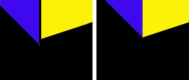
Fig. Close up of two planes with a result after snapping the points
