Cutting Planes
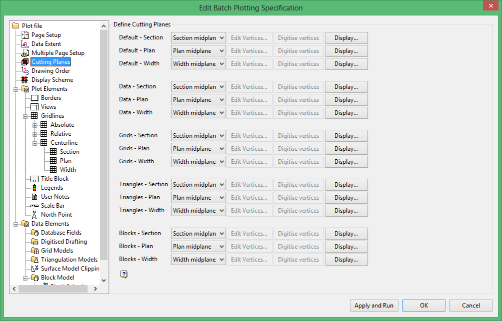
Use this section to configure the cutting planes used by Batch Plotting when slicing data, block models, grid models and triangulations. This section also to modify, from the default mid-section position, the orientation of the plane that intersects the data.
You may want to have a cutting plane that is parallel to your underground mine development that lies on an approximately 3% dipping plane.
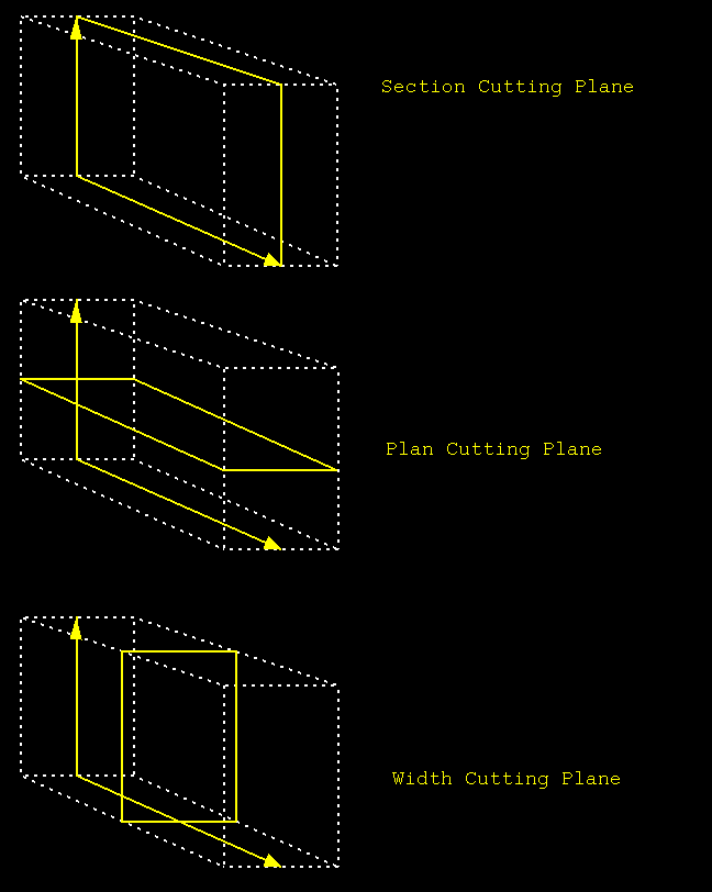
You can set default cutting planes that you can use for all other data elements or you can set cutting planes individually for each data element. It is possible to use section midplanes, plan midplanes, width midplanes or a user defined plane as cutting planes in each view.
Cutting Planes
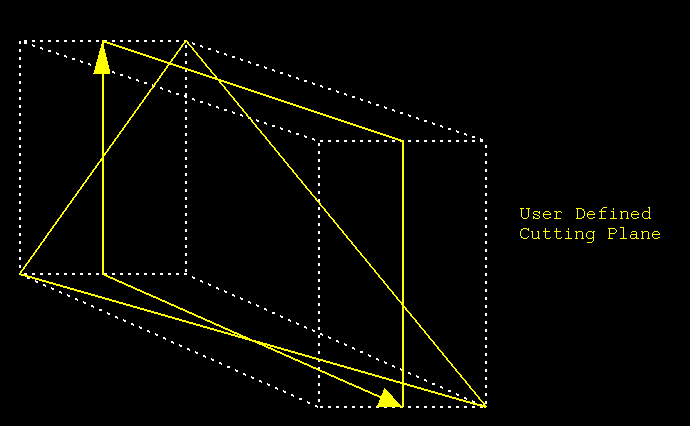
User Defined Cutting Plane
Default Cutting Planes
If you want to set default cutting planes that you can use with each data element, then specify the planes in the default section of the panel and choose Use Defaults for the other data elements.
Select, from the drop-down list, for each view the type of cutting plane that you want to use. You can display the cutting plane on the extents by using the Display button. Once selected, the Underlay display parameters panel displays.
Display as underlay
Select this check box to display the cutting plane.
Colour
Select the colour for the cutting plane.
Line Style
Select the line style for the cutting plane.
Pattern
Select a pattern for the cutting plane.
Remove on exit
Select this check box to remove the underlay that contains the cutting plane when you exit Batch Plotting.
If you select Use Vertices, then the Edit Vertices, and Digitise vertices buttons will be selectable.
A user defined cutting plane is defined by three points. These points can be entered manually (by using the Edit Vertices button) or digitised (by using the Digitise Vertices button). Once the Edit Vertices button is selected, the Define cutting plane by vertices panel displays.
Click in a cell and enter the coordinate value for the three points that will define the cutting plane.
Once the Digitise Vertices button is selected, you are prompted to digitise the vertices of the cutting plane. Use the Snap to Object ![]() or Snap to Points
or Snap to Points ![]() modes to ensure accurate placement of the plane.
modes to ensure accurate placement of the plane.
Data Elements, that is Data, Grids, Triangles and Blocks
The method for setting cutting planes for each of the data elements is the same as for setting the Defaults. However, to use the Default settings, then select Use Defaults from the drop-down lists.
Related topics

