Grid Models
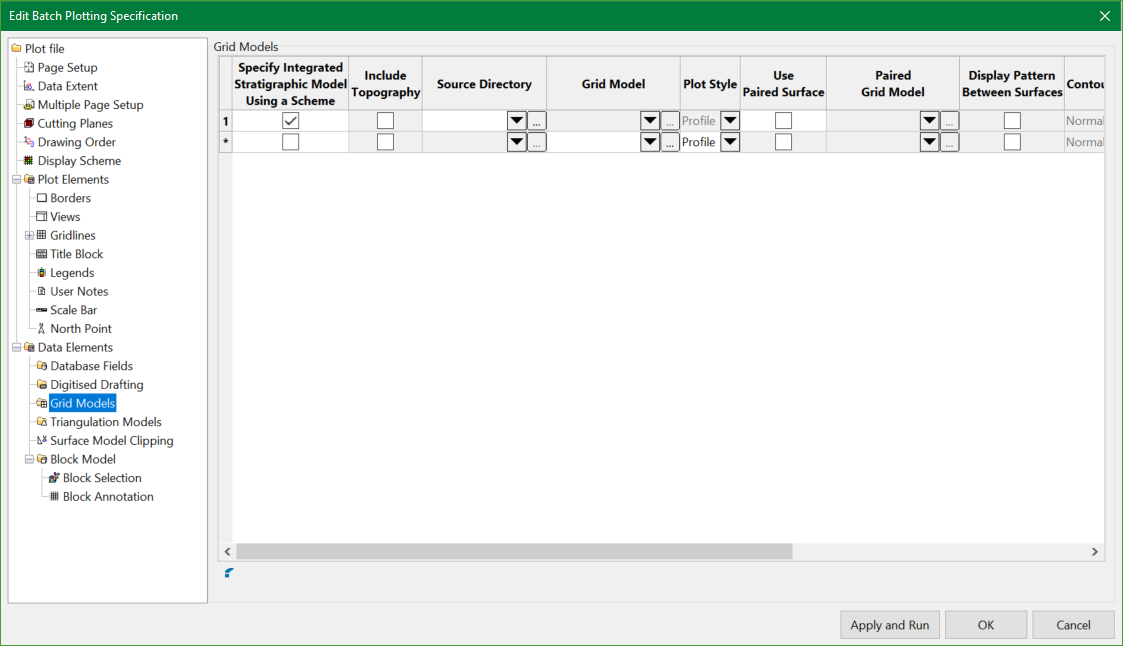
Specify Integrated Stratigraphic Model Using a Scheme
Select this check box to specify a strata scheme as a method of selecting grids to be included in the plot. Cells in columns that are no longer applicable, such as Grid Model, will be shadowed once you click in a different column.
Note: The strata scheme can be set up in the Attributes column.
Refer to the Legend Editor option for information on how to create a strata scheme. The legend should be based upon the names of the horizons present in the stratigraphic model being plotted.
Include Topography
Select this check box to plot the topography grid, as well as other grids specified in the legend.
Source Directory
This column is enabled only if the Specify Integrated Stratigraphic Model Using a Scheme option is selected. This allows users to specify a location containing the grids to be plotted.
Grid Model
Specify the grid model that you want to include in your plot. Click  to navigate to other directories or enter the path name for the grid model using up to 256 alphanumeric characters. The drop-down list contains all the grid models in your current working directory. Note that cells in columns that are no longer applicable will be shadowed once you click in a different column.
Note: The wildcard * can be used in the model name to represent multiple model files.
Plot Style
Select the plotting method (Non-profile, profile and contour).
Non-profile
Select this option to plot the entire grid (in the extents of the plot).
Profile
Select this option to plot a line where the grid intersects a specified section line.
Contour
Select this option to be able to create contours during the plotting process.
Use paired surface
If using the Profile plot style, select this check this box to create a cross section plot (in plan view) of an upper and lower surface; for example: a structure floor and roof. This option is not available with styles other than Profile.
Paired grid model
Specify the grid model to include in your plot. The drop-down list contains all of the grid models in your current working directory. Click to navigate to other directories.
Display pattern between surfaces
Select this check box if you want the area between the surfaces to contain a pattern. See Attributes for assistance with setting a pattern.
Contour Type
If using the Contour plot style, select from the drop-down list the desired contouring method (Normal, One Level and Scheme). This field is not available with styles other than Contour.
Normal
Select this option to create contours at user specified major and minor intervals.
One Level
Select this option to create one contour at a user specified level.
Scheme
Select this option to create contours as per a specified scheme. Refer to the Analyse > Legend Edit > Legend Editor option for information on how to create a contour scheme.
Attributes
Click to display the Grid Model Attributes panel.
Contour Attributes
If using the Contour plot style, click to display the grid's Grid Model Contour Attributes panel.
Include Model in Section, Plan and Width view
Check the views in which you want to include the grid model.
Related topics

