Creating a new project
Source file: creating-a-new-project-field.htm
To start monitoring with Sentry Field at a new physical location, you first need to start a new project.
To create a new project:
-
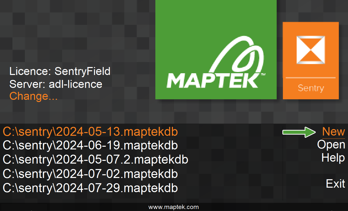
On the splash screen, click New.
-
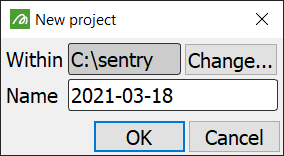
By default, Sentry will create new projects within C:\sentry. To save the project to a different folder, click Change... and browse to the new location.
-
Enter a new name for your project, if required.
-
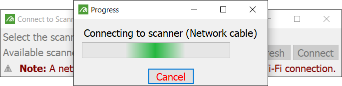
Click OK. Sentry will launch and connect to the scanner.
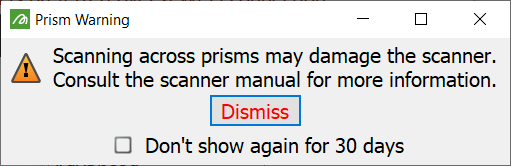
Once a connection is established the scan prism warning will display. Dismiss the warning to continue.
Creating a scene
After launching Sentry Field with a new project you must create a new scene representing your setup location. The Create Scene wizard will open to guide you through this process. See Introduction to Scenes for an explanation of scenes.
If you are connected to a scanner, you can choose to either create an unpositioned or a positioned scene. Alternatively you can create a scene from an existing scene archive.
|
|
| Creating an unpositioned scene | |
| Creating a positioned scene | |
| Importing from a scene archive | |
Note: If you select Cancel the application will close.
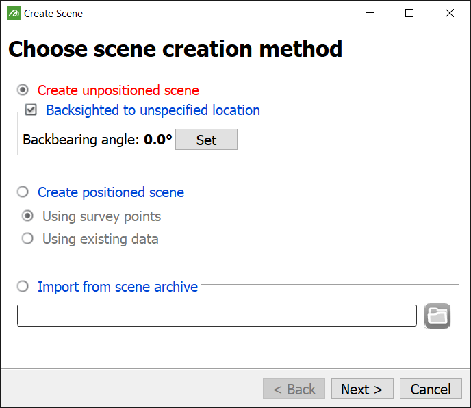
Creating an unpositioned scene
Choose Create unpositioned scene if the setup is not a known surveyed location.
Note: If you create an unpositioned scene, you can still reposition without coordinating, if required, during the scene’s lifetime.
-
If the scanner can be backsighted, select Backsighted to unspecified location.
-
Adjust the scanner backsight. See Backsighting a scanner in the scanner operator manual.
-
Click Set to apply the backbearing angle to the scanner’s current bearing.
-
Click Next >. Sentry will prompt you to define the scene region and settings. See Define the scene region and settings
Creating a positioned scene
Note: For positioned scenes to work with Gen 2 scanners (i.e. 8820) make sure the scanner is level.
Choose Create positioned scene if the setup is at a known surveyed location or you have existing data. There are two methods to specify the location, as described below.
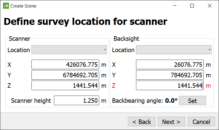
Using survey points
If you have the scanner location and backsight, choose Using survey points, click Next >, then proceed as follows:
-
Enter the scanner and backsight locations.
-
Enter the scanner height as the height offset of the surveyed location to the bottom marker on the scanner.
-
Click Next > then go to Define the scene region and settings
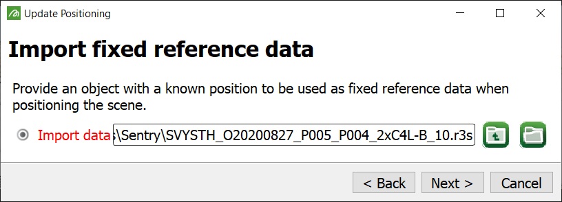
Using existing data
If you can supply an existing registered scan, surface or point set, choose Using existing data, click Next >, then proceed as follows:
-
Provide a surveyed scan or an object (for example, a surface created in PointStudio) to be used as the fixed reference data when positioning the scene.
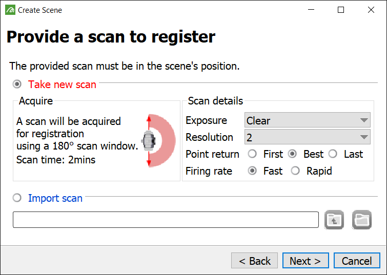
After providing this data, you will be asked to provide a scan representing the scene to register.
-
Select either Take a new scan and set the parameters for a new scan, or Import scan, then browse to and select a previously created scan.
-
After selecting the scan to register, click Next > to open the registration tools. See Positioning > Registering the scene for more instructions on using the registration tools.
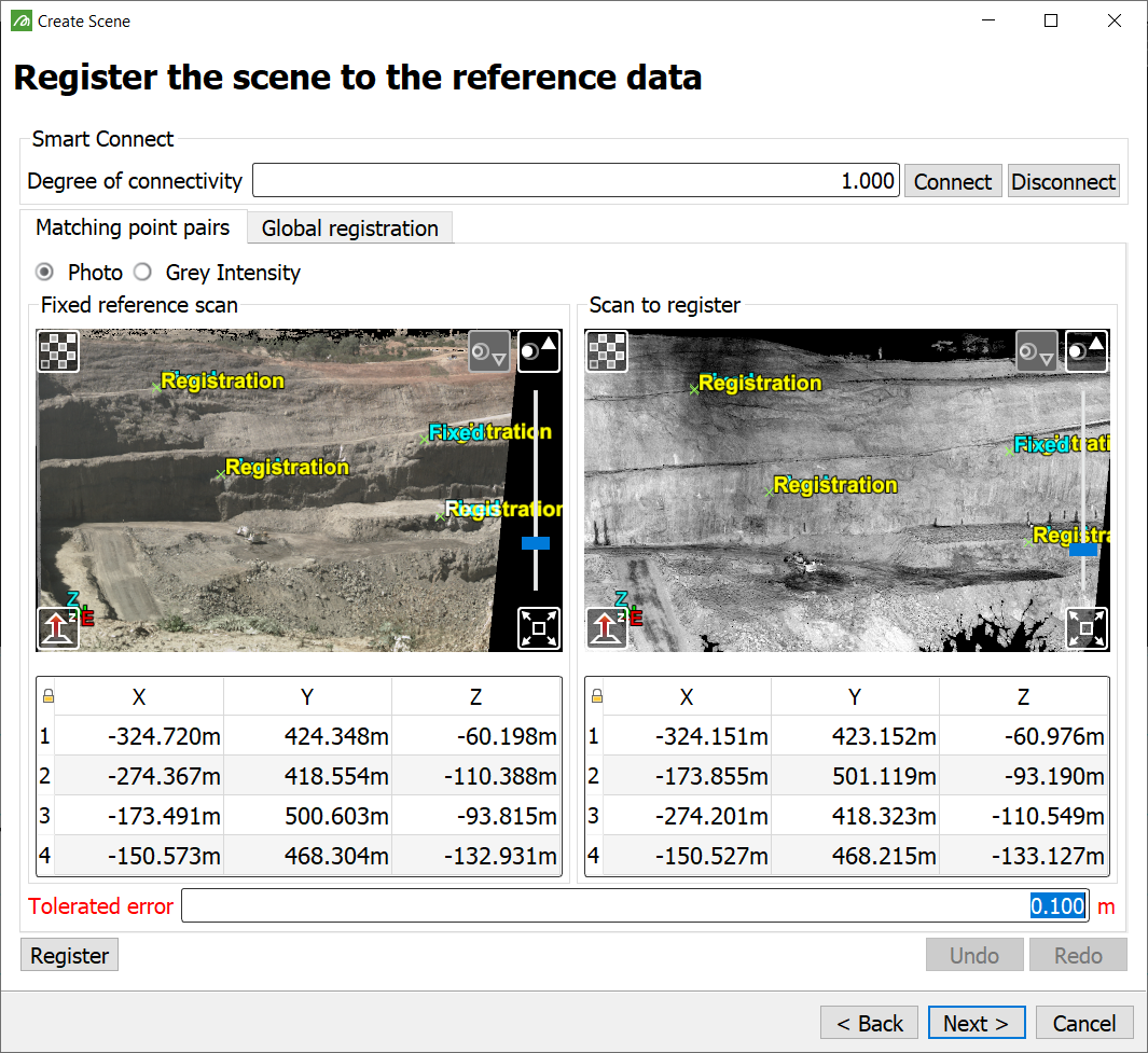
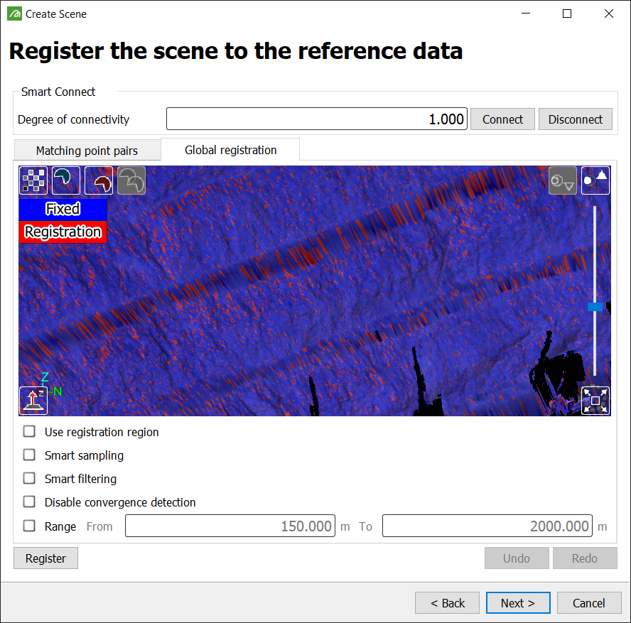
When the scan to register (the red scan, per the Global registration tab, representing the scene) aligns with the fixed reference data (the blue data, representing the real world), click Next >, then continue with Define the scene region and settings
Note: If you select Cancel the application will close.
Define the scene region and settings
After you click Next >, Sentry will take a preview from the scanner. Check the preview appearance and make any necessary adjustments.
Exposure setting
If the preview is under- or over-exposed, you can adjust the Preview exposure and take a new preview. Set the exposure setting for the camera from the drop down list that suits your environment. This is for the preview only; Sentry will automatically determine the best settings when scanning. Exposure settings may include the following, depending on the specific scanner in use:
-
Photo (Clear)
-
Photo (Overcast)
-
Photo (Sunset)
-
Photo (indoors)
-
Underground (Bright)
-
Underground (Average)
-
Underground (Dim)
-
Range
Scene region and settings
Sentry will ask you to define the scene region and scanner settings. The scene region defines the extent of the window to scan.
-
To define the scene region, draw a window on the preview image.
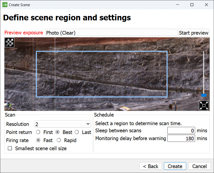
Set the scan and schedule options below, as required.
Note: Some scan option combinations may not be compatible. The software will display a warning and not allow the selection to be saved.
|
The resolution numbers give an indication of relative scan point density, both horizontally and vertically. The higher the number, the denser the scan points. Refer to your scanner manual for detailed information. Resolutions available are: 1, 2, 4, 8 and 16 (depending on the scanner model). |
|
|
The laser beam may return multiple signals from different obstacles in the path of the beam. Choose which reflections to prioritise.
Refer to your scanner manual for detailed information. See also: Scan points, cells and zones. |
|
|
The firing rate is the speed at which the laser fires when scanning. Higher firing rates result in quicker scanning, but reduce the maximum range. Firing rate options are: Normal, Fast, Rapid, and Ultra (depending on the scanner model). Note: Mirror and scan head speeds adjust to compensate for firing rate so that resolution is not affected. Refer to your scanner manual for detailed information. |
|
| Smallest scene cell size |
Select this option to increase the level of detail beyond that provided by the maximum resolution. With this option selected, cells will consist of 2x2 point-grids rather than the standard 3x3. Note: Point density is not increased, so this option may reduce accuracy. |
| Sleep between scans | Sleep between scans defines a period of scanner inactivity between scans. Enter 0 to cause the scanner to scan continuously. |
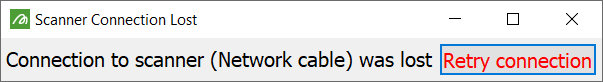
Sentry periodically checks whether scanning or processing has stalled. Monitoring delay before warning specifies the amount of time to wait when a such a stall has occurred, before generating a warning. For example, if a scan takes 3 minutes to complete and 10 minutes is entered for the delay, event code E-23 (Scanner has stalled) will be triggered if there are no new scans after 13 minutes. If 13 minutes pass and the processing of the previous scan has not completed in time, event code E-24 (Scan processing has stalled) will be triggered. If at any stage the scanner disconnects, the message below will appear, prompting reconnection.
If you are operating an M20 scanner in extremely low temperatures, it may need to warm up. Include time in the monitoring delay to allow for warm-up in these conditions. For example, if operating at -20°C add an extra 40 minutes for warm-up time. |
-
Click Create to start monitoring the scene.
Note: Scan time is automatically calculated by the software.
Note: If you select Cancel the application will close.
Importing from a scene archive
The final method requires a scene that has previously been archived (see Archiving). Proceed as follows:
-
Navigate to, and choose the relevant
.ziparchive and click Next >.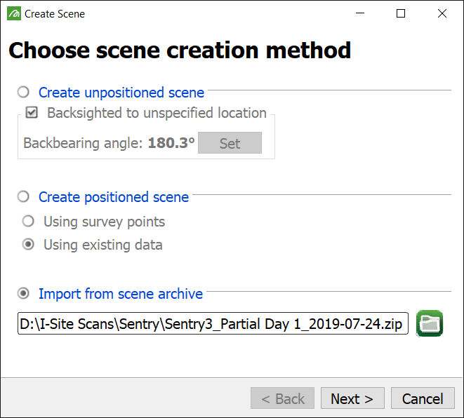
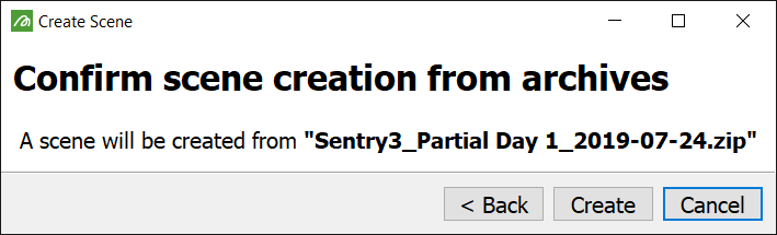
The archive will be validated and a final confirmation window will open.
-
Select Create to proceed with creating the scene, or < Back to return to the previous screen.
-
Once the scene has been created, click Finish to close the Create Scene panel.
Sentry will automatically start monitoring.
Note: If you select Cancel the application will close.
