Configuring
Source file: configuring.htm
This section provides instructions on configuring scenes to suit the specific job.
Setting the measurement base and filters
![]() Filters and Base
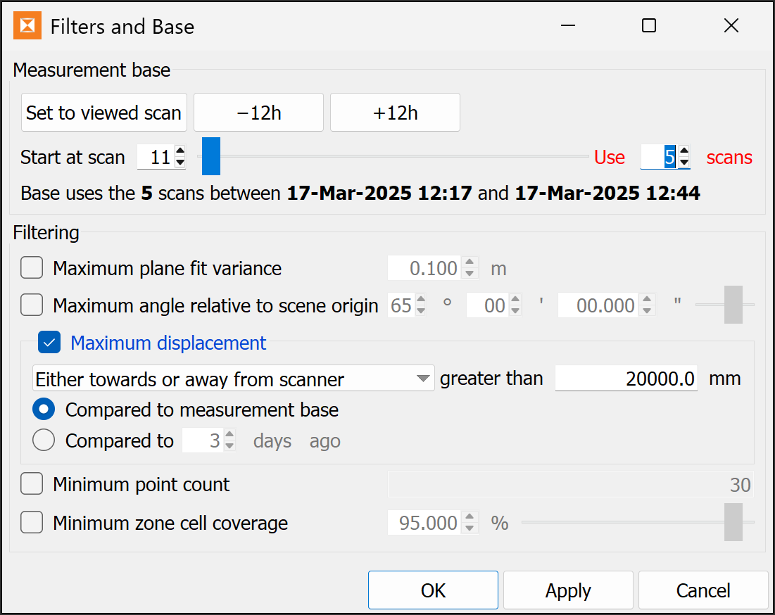
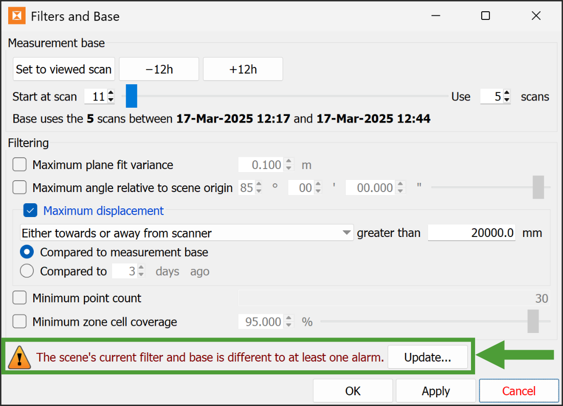
Filters and Base
Measurement base
The measurement base is the reference scan from which all displacement calculations are performed. Changing this will update graphs and heatmaps.
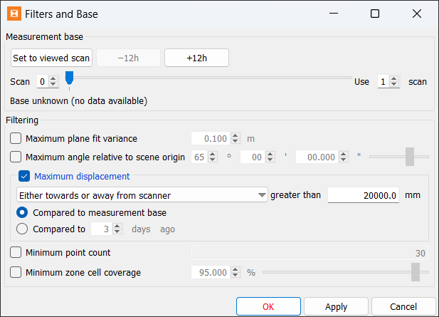
You can either use a single scan or an average of multiple consecutive scans as the measurement base.
To set the measurement base, do the following:
-
Select the first scan of the base with one of the following methods:
-
If the scene is showing the required scan, click Set to Viewed scan.
-
Enter a scan number in the Start at scan field.
-
Drag the slider to the required scan number.
-
-
Enter the number of scans to use in the Use n scans field.
Filtering
You can filter the scene to hide cells that meet various conditions. Hidden cells are excluded from graphs and alarms. Whenever filtering settings are changed and applied, the scene visualisation updates to reflect those settings. Select the required filter check boxes, then set the parameters, as follows:
-
Maximum plane fit variance specifies how well the cell fits the scan points. A lower variance means a better fit to the data. For example, a flat wall would have a low variance, whereas a sphere would have a high variance.
-
Maximum angle relative to scene origin specifies the direction of the cell relative to the look direction from the scene origin. This is used to hide oblique cells.
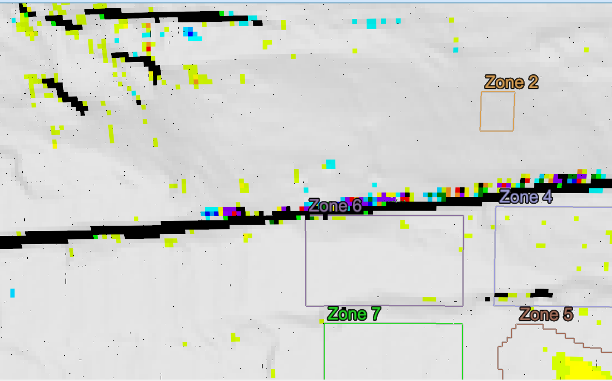
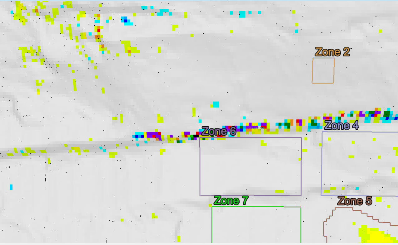
Maximum angle relative to scene origin set to 65° (left) and 85° (right).
-
Maximum displacement specifies how far a cell’s range must differ from its base before being filtered out. You can use this, for example, to mask out vehicles driving in front of the wall. The direction of displacement is selectable from the drop-down list. The displacement can be measured from either the base scan or a scan from a specified number of days ago. Select one of the following:
-
Compared to measurement base
-
Compared to n days ago, then specify the number of days.
Or
-
-
Minimum point count indicates that any cells made up of fewer points than specified will be ignored.
-
Minimum zone cell coverage is the required percentage of cells to be valid within a zone. Zone graph data will be ignored if the zone does not have enough valid cells.
Updating alarms
When you create an alarm, the current filter and base settings are applied to the alarm. When you change the scene’s filter and base settings, existing alarms are not automatically updated. When there are alarms that do not match the filter and base settings, the Filters and Base panel appears as follows:
-
To apply the new filter and base settings to all alarms, click Update..., then Yes to confirm.
The warning and Update... button will then disappear.
Note: If you start to change filter and base settings before updating alarms, the Update... button will be disabled until after you apply the new settings. This ensures that the settings are applied consistently.
-
Use the Edit Alarms tool to update individual alarms. Click Edit for the alarm in question and click Update..., then Yes to confirm.
See also: Alarms and Events > Creating and configuring monitoring alarms
Setting the registration region
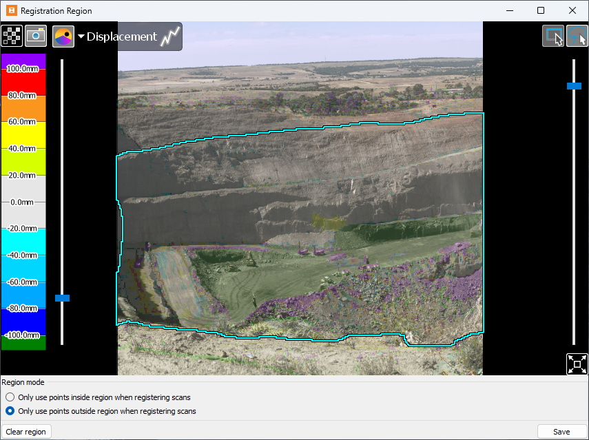
The registration region is a special zone that is used when performing registration. Sentry uses this zone to filter out data from the reference registration data (that is, the initial scan and the previous scan) when registering the newly acquired scan. Define the registration region to exclude areas known to be moving that would adversely affect registration if included. For example, trees or other vegetation on a hillside that sway in the wind.
To set the registration region:
-
 Set Registration Region
 -
Set the Region mode to define the registration regions as either inside or outside the defined region.
Tip: Select Only use points outside region when registering scans then, in the next step, draw regions of operational activity to be excluded from the registration region.
-
Using the rectangle (
 ) or freehand (
 ) selection tool, draw a region. If necessary, click Clear region to clear the region and start again.
Tip: Hold Shift to add more areas after drawing the first registration region.
-
Click Save.
|
|
|
The Registration Region panel with an area to exclude drawn on the scene. |
Note: If no region is defined, or you clear the existing region and save it, the entire scene region will be used for registration.
Rolling back a scene
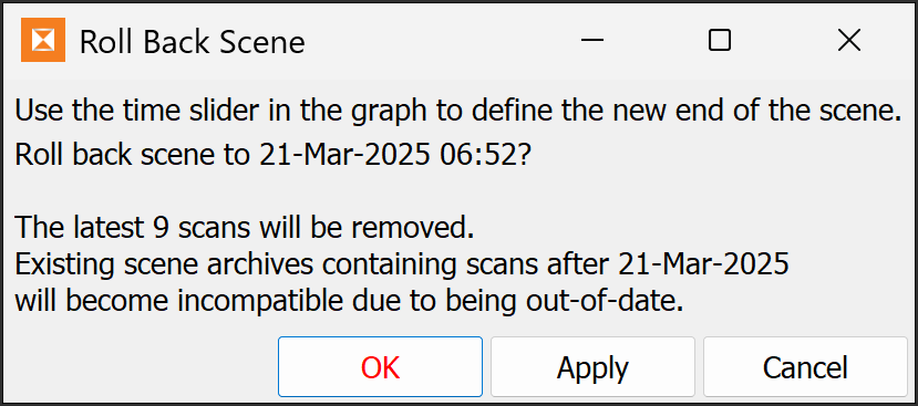
If necessary, you can roll a scene back to scans from an earlier date and time to correct mistakes such as failing to register a scan correctly. Rolling back will effectively delete the data so the problem scans can be replaced.
The most common causes for registration problems are backsighting to an incorrect position, failing to backsight at all when resuming scene monitoring, and not registering the scanner position properly when moving the scanner and using the positioning tools. If this happens, scans will be misregistered when monitoring is resumed.
To roll back a scene, do the following:
-
 Roll Back
The Roll Back Scene panel will appear.
-
Drag the time slider in the graph to set the roll-back point. The panel will indicate the date and time of the new end-of-scene.
-
Click OK or Apply.
A second Roll Back Scene panel will appear.
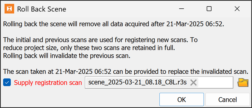
Note: Due to space limitations, Sentry does not keep every scan in the database. Therefore, the latest scan must be re-imported because it will be used for registration with the next scan taken.
-
If necessary, browse to, and select the replacement latest valid scan.
Note: If you do not provide a registration scan in Sentry Office, you will either need to disable registration or supply a registration scan when adding a new scan. Also, you will not be able to resume the scene on loading the project into Sentry Field.
-
Click OK to finish.
Configuring zones
Following are instructions for working with zones.
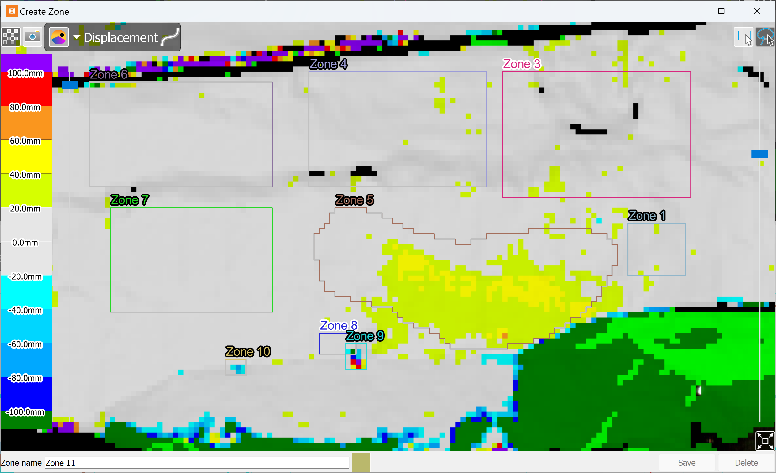
Creating and editing zones
To create a new zone:
-
 Create.
This will open a new view of the scene where you can define the zone.
-
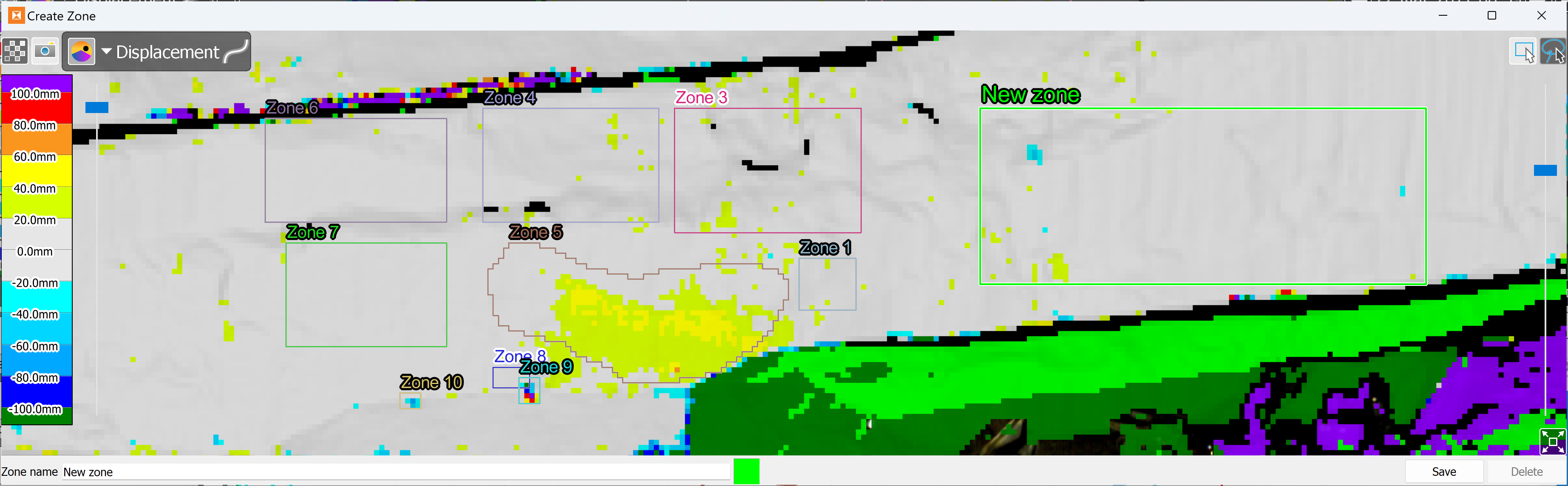
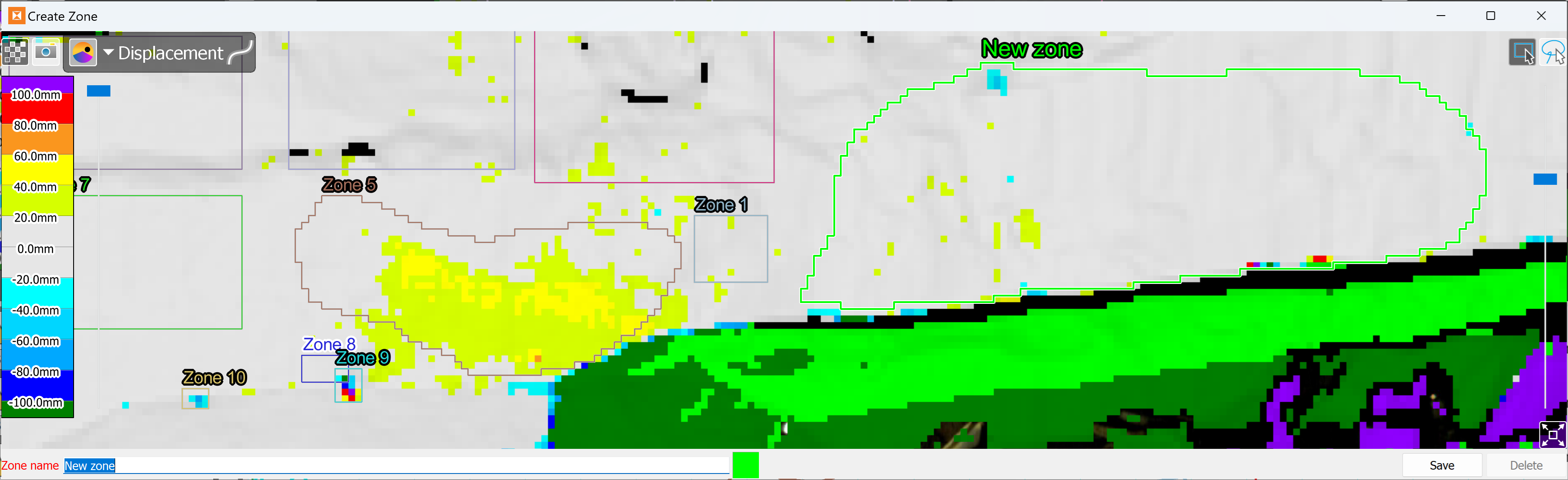
Use the rectangle (
) or freehand () selection tool to draw a zone. -
Click and drag on the view to define the shape of the zone.
-
Edit Zone name, if required.
-
Optionally, change the zone colour for better contrast. Click the colour swatch and select a different colour.
-
Click Save to save the zone.
|
|
|
Creating a new zone in Sentry |
|
|
|
Defining a zone using the rectangular selection tool |
|
|
|
Defining a zone using the freehand lasso selection tool |
Editing zones
To edit a zone:
-
Select the zone in the scene viewer or from the zone selector in the graph view.
-
 Edit.
Edit. -
Draw a new zone area, enter a new zone name or change the zone colour, as required, following the instructions above.
-
Click OK or Apply to finish.
Deleting zones
To delete zones:
-
Select a zone by clicking in it in the scene view, or by selecting it from the zone selector in the graph view. Hold down the Shift key while clicking to select multiple zones in the scene view.
-
 Delete.
 -
When prompted, choose Yes to delete or No to cancel.
Exporting zones
Occasionally you may want to set up Sentry in a different location to monitor the same zone of interest on a surface. Use zone export and import to re-use zones between scenes at different setup locations.
To export zones from your scene:
-
Select the zones you wish to export from the zone selector or the scene viewer.
-
 Export.
 -
Choose a location to save to and click Save. Sentry will save the selected zones into a single Maptek object file (
.maptekobj).
Importing zones
You can import zones created in Sentry or PointStudio that were exported as a Maptek object file (.maptekobj) file.
To import zones from a Maptek object file into your scene:
-
 Import.
 -
Select the Maptek object file containing the zone objects. The zone objects must be polygons or surfaces.
-
Click Open.
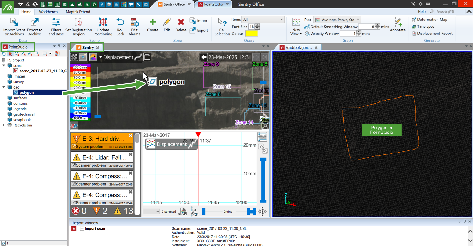
Importing zones from PointStudio into Sentry
Zones can be created or edited in PointStudio and then imported into Sentry.
To do this, you need to ensure that the zones in PointStudio are in the same position as the scene in Sentry. The scene in Sentry must be positioned. See Positioning > Assigning a position to a scene for instructions.
To create zones in PointStudio and transfer them into Sentry:
-
Import a scan or other data in the area you wish to create the zones.
You can import scans archived in the Sentry project. These scans are located in the folder named
sentry.scans.archivein the Sentry project. Your Sentry project is a folder with a.maptekobjextension. -
Create polygons or surfaces representing your zones of interest.
-
Transfer the zones into Sentry. There are two ways to do this:
-
If you have PointStudio and Sentry Office open in the same Workbench instance, you can drag the zone objects (including containers of zone objects) directly from the PointStudio project explorer and drop them onto the scene viewer.
-
Export the zone objects as a Maptek object file (
.maptekobj), then import the.maptekobjinto Sentry Office. See Importing zones, above for details on how to import zones from.maptekobjfiles into Sentry Office.
-
