Dimensions
Instructions
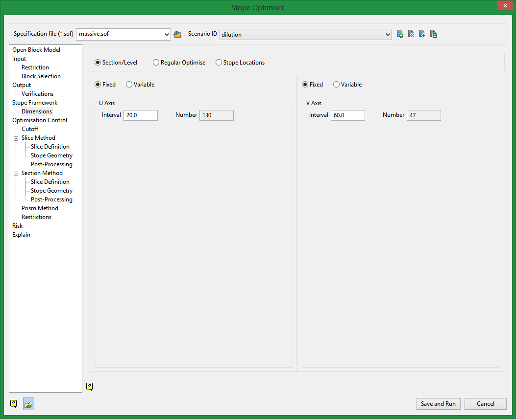
On the Underground menu, point to Analyse, click Stope Optimiser, and then select Dimensions from the tree menu on the left to display the Dimensions pane.
Settings
Section/Level - Fixed
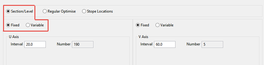
This method allows you to select an Interval spacing based on the S tope orientation plane that you selected on the Stope Framework pane. The Number of stopes will be automatically calculated.
U axis
Corresponds with the first axis of your stope orientation plane.
V axis
Corresponds with your second axis of the stope orientation plane.
Example
With an XZ stope orientation plane the U axis corresponds to the X axis and the V axis corresponds to the Z axis.
Section/Level - Variable
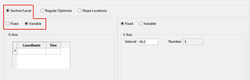
This method allows you to select an axis, coordinate and size for the stopes at the specified coordinates.
U axis
Corresponds with the first axis of your stope orientation plane.
V axis
Corresponds with your second axis of the stope orientation plane.
Example
If you selected XZ as the Stope orientation plane, a U axis with a coordinate of 74000 and a size of 20, the result would be that only stopes along the 74000 easting would be created. Additionally those stopes would have a dimension of 20 in the X direction.
Multiple coordinates with associated sizes may be specified, resulting in an irregular framework.
Regular Optimise
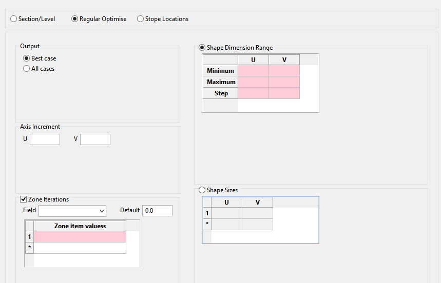
Zone Iterations
Use this option to run framework optimisation on a zone by zone basis.
Shape Dimension Range
Provide an acceptable range of dimensions for each axis. This will be used to determine the optimal stope sizes.
Minimum
Define the minimum acceptable stope size for each axis. This will then be used to determine an optimal stope size.
Maximum
Define the maximum acceptable stope size for each axis. This will then be used to determine an optimal stope size.
Step
Define the step size for each axis. The step size should be a sub-multiple of the (maximum - minimum) stope size. The step will be used as the interval to determine the optimal stope size.
Shape Sizes
Select this option to define stope sizes based on a list of stope shape sizes. This is similar to the shape dimension range method, but instead of defining a range you explicitly provide a list of acceptable stope sizes.
Stope locations
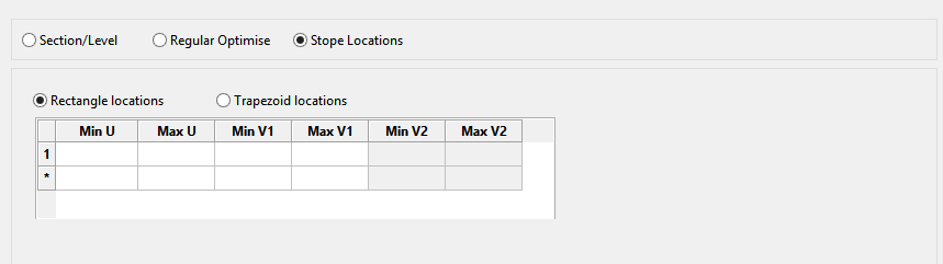
The Stope Locations method uses one of two user specified methods for defining stope locations. Both methods use U and V axes to define stope locations and shapes. The U axis corresponds with the first axis of your stope orientation plane. The V axis corresponds with your second axis of the stope orientation plane.
Rectangle Locations
This method uses minimum and maximum U and V coordinates to define stope positions. If you have selected an XZ stope orientation plane the U axis corresponds to the X axis and the V axis corresponds to the Z axis. Multiple rows can be specified to define the various stope locations
Trapezoid Locations
This method is similar to the rectangle method, but utilizes and additional input on the V axis. This results in irregular stope shapes. This can accommodate sloping tops or bottoms to the stopes. Multiple rows can also be specified to define the various stope locations and shapes.
Example: A minimum and maximum U of 55500 and 55510 and a minimum and maximum V1 of 9740 and 9770 would result in stopes that are 10 units wide by 30 units high. The length of the stopes would be calculated and would depend on the stope parameters and cutoff conditions.
Related Topics
Section Method Slice Definition
Section Method Post Processing

