Prism Method
Instructions
On the Underground menu, point to Analyse, click Stope Optimiser, and then select Prism Method from the tree menu on the left to display the Prism Method pane.
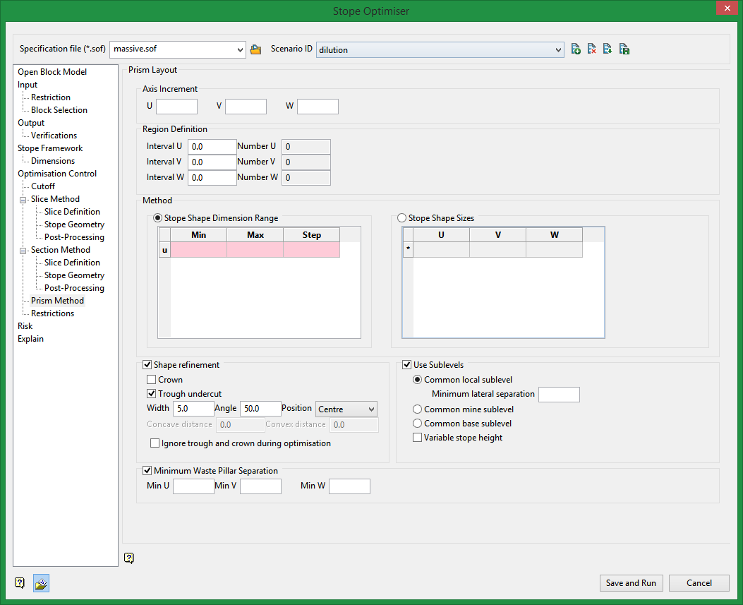
Prism Layout
For the Prism method the stope shape framework is defined as a volume in [U,V,W] consisting of cells where an individual cell is given the special name “region” for this method. Regions are used to subdivide the problem space as the optimization problem might otherwise be too big if the entire framework was a single “cell” (with NU=NV=NW=1). In each region, a set of non-overlapping stope shapes is optimised.
The choice of where to subdivide is up to the user, it might be a group of sublevels or sections for example – whatever makes geometric sense. The shape library is applied to each region in turn, and regions are optimized independently. The framework could be a single transverse section if the Prism method was used to solve the Transverse Section problem. The framework must have regular intervals on the U and V and W axes. The size of the intervals might in some cases be the minimum stope dimension. A grid increment is defined on each axis within each region. Stopes from a library of shapes will have a size that is a multiple of the grid increment. Stopes can be located at any grid increment.
Axis Increment
Framework origin increments on the U, V, and W axes.
Region Definition
Method
Select between two methods:
Stope Shape Dimension Range
Enter the Min and Max size ranges, and the Step increment.
Stope Shape Sizes
Enter the stope size for the U, V, and W axes.
Shape refinement
Crown
If the option for a crown is selected, enter the Concave and Convex distances.
Trough undercut
Enter the Width, Angle, and Position of the trough undercut.
Use Sublevels
Common local sublevel
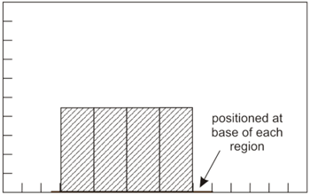
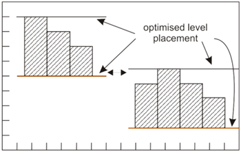
This function anchors the stope floor levels to each region’s minimum Z value.
Common mine sublevel
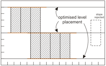
This function requires that all stopes honour the set of levels found in the optimisation run (i.e. selects the best of feasible solutions). For example, a stope optimisation solution where one stope is located at say 10m above a common-level (of say 40m) shared by other stopes would not be feasible or allowed.
Common base sublevel
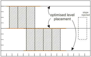
This function allows levels to vary within a region, but vertically over-lapping stopes within a minimum horizontal separation distance must have the same floor level (i.e. adjacent stopes that overlap in the vertical sense cannot have an offset in the floor, although they can optionally be displaced from a regular grid in the X,Y space). The effect is to cluster stopes into groups with each group having a shared set of sublevels.
Variable stope height
This is a function modifier for the Common mine sublevel and Common base sublevel options. Enabling this sub-option allows variable height stopes to be created between sublevels (e.g. it allows the creation of say “half-height”, “three quarter height” if these stope-shape options are specified in the shape library).
Minimum Waste Pillar Separation
Minimum waste pillar separation between stopes on the U, V, and W axis if the stopes do not abut.
Related Topics
Section Method Slice Definition
Section Method Post Processing

