Advanced
Use Stope Framework Advanced to input parameters to create an irregular framework. The Advanced panel offers different options for following methods:
- Slice Method
- Section Method
Select your method from the links above or scroll down this topic to locate Slice Method or Section Method .
Requirements
A block model must be selected from the Open Specification page.
Instructions when using Slice Method
On the Underground menu, point to Analyse, click Stope Optimiser, and then select Stope Framework > Advanced from the tree menu on the left to display the Advanced panel.
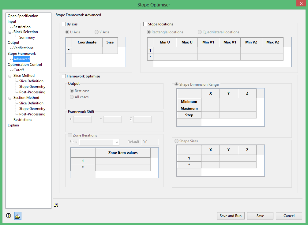
By axis
The By axis method allows you to select an axis, coordinate and size for the stopes at the specified coordinates.
The U axis corresponds with the first axis of your stope orientation plane. The V axis corresponds with your second axis of the stope orientation plane.
So if you have selected an XZ stope orientation plane the U axis corresponds to the X axis and the V axis corresponds to the Z axis.
Example: If the U axis was selected with a coordinate of 74000 and a size of 20 the result would be that only stopes along the 74000 easting would be created. Additionally those stopes would have a dimension of 20 in the x direction.
Multiple coordinates with associated sizes may be specified, resulting in an irregular framework.
Stope locations
The Stope Locations method uses one of two user specified methods for defining stope locations.
Either method uses U and V axes to define stope locations and shapes. The U axis corresponds with the first axis of your stope orientation plane. The V axis corresponds with your second axis of the stope orientation plane.
The Rectangle Locations method uses minimum and maximum U and V coordinates to define stope positions.
If you have selected an XZ stope orientation plane the U axis corresponds to the X axis and the V axis corresponds to the Z axis.
Example: Say you input a minimum and maximum U of 55500 and 55510 as well as a minimum and maximum V1 of 9740 and 9770. This would result in stopes that are 10 units wide by 30 units high. The length of the stopes would be calculated and would depend on the stope parameters and cutoff conditions.
Multiple rows can be specified to define the various stope locations.
The Quadrilateral Locations method is similar to the rectangle method, but utilizes and additional input on the V axis. This results in irregular stope shapes. This can accommodate sloping tops or bottoms to the stopes.
Multiple rows can also be specified to define the various stope locations and shapes.
Framework optimise
This will shift the framework withing the extents to find the optimal location.
You must specify a step in X, Y and Z directions. The optimizer will use this step to shift the framework and determine the optimal location.
Output
Best case : Select this option to only output the best case to the output files (the default mode).
All cases : Select this option to output all combinations of the stope size and framework to the output files (if supported by data store).
Optimise sublevel intervals : Select this check box to optimise the location and sublevel interval allowing different combinations of sublevel intervals to be identified. This can only be used where the stope step size on the Z axis equals the framework axis increment on the Z axis.
Zone Iterations
Use this option to run framework opimisation on a zone by zone basis.
Shape Dimension Range
Here you can give the optimizer an acceptable range of dimensions for each axis. This will be used to determine the optimal stope sizes.
Minimum : Define the minimum acceptable stope size for each axis. This will then be used to determine an optimal stope size.
Maximum : Define the maximum acceptable stope size for each axis. This will then be used to determine an optimal stope size.
Step : Define the step size for each axis. The step size should be a sub-multiple of the (maximum - minimum) stope size.
The step will be used as the interval in determining the optimal stope size.
Shape Sizes
Select this option to define stope sizes based on a list of stope shape sizes.
This is similar to the shape dimension range method, but instead of defining a range you explicitly provide a list of acceptable stope sizes.
Instructions when using Section Method
On the Underground menu, point to Analyse, click Stope Optimiser, and then select Stope Framework > Advanced from the tree menu on the left to display the Advanced panel.
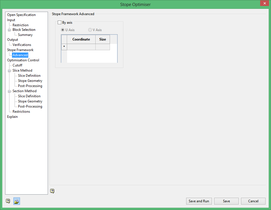
By axis
The By axis method allows you to select an axis, coordinate and size for the stopes at the specified coordinates.
The U axis corresponds with the first axis of your stope orientation plane. The V axis corresponds with your second axis of the stope orientation plane.
So if you have selected an XZ stope orientation plane the U axis corresponds to the X axis and the V axis corresponds to the Z axis.
Example: If the U axis was selected with a coordinate of 74000 and a size of 20 the result would be that only stopes along the 74000 easting would be created. Additionally those stopes would have a dimension of 20 in the x direction.
Multiple coordinates with associated sizes may be specified, resulting in an irregular framework.
Related Topics
Section Method Slice Definition
Section Method Post Processing

