Output
Use Output to define the directories in which files are saved, assign prefixes to filenames, and define the colours to be used by each output. All fields in this panel are required.
Note: Unless you have used the Browse button to select the database name and various directories, only the specific filename displays, even if you entered the full path name.
Requirements
A block model must be selected from the Open Specification page.
Instructions
On the Underground menu, point to Analyse, click Stope Optimiser, and then select Output from the tree menu on the left to display the Output panel.
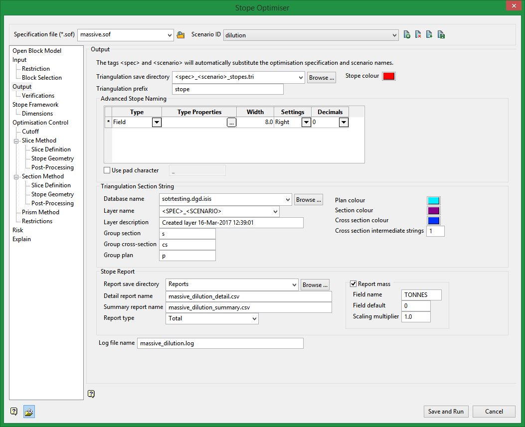
Output
Use this section to define the location for the output files resulting from the stope optimisation process.
Triangulation save directory
Enter the directory where you want to save the stope triangulations. Type in the full path name or browse to the desired location. The suffix should be.tri. Click Browse to select a file from another location.
Triangulation prefix
Enter the characters to be added in front of the triangulation name. This prefix will be added to the triangulations that are created with this stope optimiser option. For example, Prefix_Advanced Naming_Counter.00t.
Stope colour
Click to select a colour for the resulting triangulation. This will be used for the output wireframe triangle.
Advanced Stope Naming
The default method of naming stopes is to number the stopes in the sequence generated, starting from one. Advanced Stope Naming provides a way to name according to the spatial location of the stope, the stoping method, primary/secondary status, and ore type or ore classification. The stope name is a string of up to 20 characters. Names are made up of 'parts. Parts are concatenated left to right in the sequence that is defined to form the final name.
The Advanced stope naming selections are optional and can be selected to apply to the stope naming convention.
Select the type from the drop-down list for the Type. The list selection consists of Auto, Expression list, Field, Fixed, and Position counter.
Depending on the Type selection, different entries will exist for the Type Properties section.
Auto
If the Type is Auto, for the Type properties, select the Auto source from the drop-down list of selection types.
Expression list
If the Type is Expression, for the Type properties, enter an expression string and for each expression, enter a value for the expression if the expression is true.
Field
If the Type is Field, for the Type properties, select field variable from the drop-down list, and enter a numeric value for the Field default if the Field variable selected is a numeric type, otherwise enter an alpha-numeric value for the Field default if the Field variable selected is alpha-numeric.
Fixed
If the Type is Fixed, for the Type properties, enter an alpha-numeric value for the Fixed string.
Progression counter
If the Type is Progression counter, for the Type properties, select the Axis from the drop-down list. The list consists of u, v, and w. Select the Progression from the drop-down list. The progression selections include Start from min and Block from max. If the Letter count button is selected, then enter an alpha-numeric value for the Start and an alpha-numeric value for the Step value, otherwise if the Number count button is selected, then enter a numeric value for the Start and a numeric value for the Step, each with a maximum of two decimal places.
Triangulation Section String
Use this section to define where the plan, section and cross-section output strings produced from the stope optimisation will be housed - specifically the database and the layer.
Database name
Select the database into which the triangulation section string(s) will be housed. The drop-down will list all of the.dgd.isis files available from in the current working directory. Click Browse to select a file from another location.
Layer name
Enter a new layer name or select the design database layer into which the triangulation section string(s) will be housed. The drop-down will list all of the layers available from the current working directory.
Layer description
Enter a description for the saved layer using alphanumeric and/or special characters.
If this field is left blank the layer description will automatically be populated with the date/time of layer creation.
Plan colour
Click to select a colour for the plan strings. This colour will represent the plan outline strings in the design database.
Section colour
Click to select a colour for the section strings. This colour will represent the section outline strings in the design database.
Cross section colour
Click to select a colour for the cross-section strings. This colour will represent the cross-section outline strings in the design database.
Group plan
Enter the desired group code for the plan strings. This identifier will automatically be assigned to the group attribute of the design or CAD data.
Group section
Enter the desired group code for the section strings. This identifier will automatically be assigned to the group attribute of the design or CAD data.
Group cross-section
Enter the desired group code for the cross-section strings. This identifier will automatically be assigned to the group attribute of the design or CAD data.
Stope Report
Use this section to identify the directory where the reports produced from each computed stope shape will be housed. Data includes the number for each stope shape, as well as the tonnes and grades contained in each shape. A detailed report is always required for output. The style of the detailed report can be controlled through the Report type option.
Report save directory
Select the desired location to save the Report file and Log file reports that are generated from the stope optimisation process. The drop-down list displays all folders found in your current working directory. Click Browse to select a file from another location.
Detail report name
This label displays the name and location of the .csv file that was created during the stope optimisation process. The file will be named <specification>_<scenario>.csv. The report will be saved to the Report save directory location.
Summary report name
The summary report will provide a total for all stopes in the run, and a count of the number of stopes generated.
Report type
Report type options are Total, Summary, or All.
Total
A one line stope summary.
Summary
Provides a breakdown or ore, waste and total.
All
Provides a breakdown of near/far, hanging wall/floor wall, internal, total waste, void, ore, total (includes "Total" and "Summary")
The field RETYPE will be generated in the report to indicate the report style chosen.
Log file name
This label displays the name of the .log file created during the stope optimisation process. All optimisation processing information will be saved to this file. The file will be named <specification>_<scenario>.csv. The log will be saved to the
Report save directory location.
Related Topics
Section Method Slice Definition
Section Method Post Processing

