Section Method: Stope Geometry
Use Section Method : Stope Geometry to define the geometry of the stope. These measurements can be based on ground conditions and/or on equipment.
Requirements
A block model must be selected from the Open Specification page.
Instructions
On the Underground menu, point to Analyse, click Stope Optimiser, and then select Section Method > Stope Geometry from the tree menu on the left.
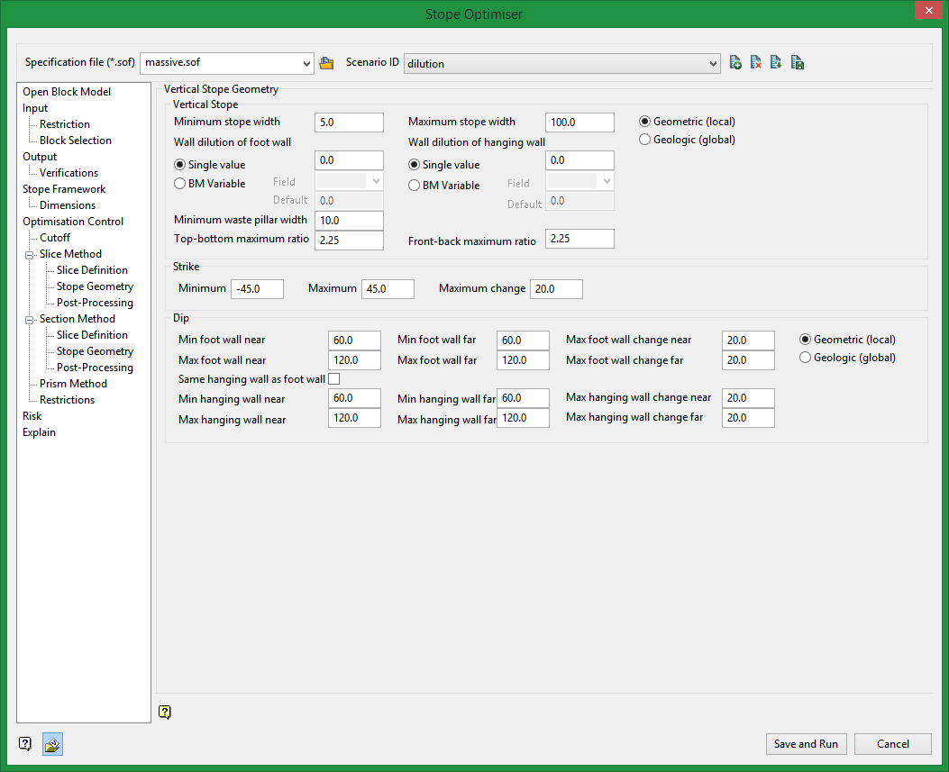
Vertical Stope
Geometric/Geologic
Wall angles, dilution and structure orientation can be specified by hanging wall and footwall orientation for the Vertical case, and this is called a Geometric definition of orientation. The alternative is to specify the behaviour at thenearandfarside of the orebody where near is the lower coordinate and far is the higher coordinate, and this is termedGeologic. In theGeometriccase the orientation can change from hanging wall to footwall and back, over the vertical height of the orebody. In the Geologic case, the orientation is fixed over the vertical height of the orebody.
Minimum stope width
Enter the minimum mining width (>/= 0.0) allowed for this stope shape. The default is 5.0.
Maximum stope width
Enter the maximum mining width allowed for this stope shape. The value must be greater than the defined minimum. The default is 100.0
Wall dilution of foot wall
Enter the amount of wall dilution (>/= 0.0) that is allowed for the foot wall. The default is 0.0.
Wall dilution of hanging wall
Enter the amount of all dilution (>/= 0.0) that is allowed for the hanging wall. The default is 0.0.
Minimum waste pillar width
Enter the minimum waste pillar width (>/= 0.0). A waste pillar is inserted once the maximum stope width/length has been met. It inserts the piller in-between adjacent stopes in the calculated direction. If you mine up against fill and do not require a waste pillar you can put in a small number (0.01 for example). The optimizer does not support a zero value for waste pillar width.
Top-bottom maximum ratio
Enter the Maximum acceptable ratio of the dimension of the top of the stope and the dimension of the bottom of the stope. The default is 20.0.
Front-back maximum ratio
Enter the m aximum acceptable ratio of the dimension of the front of the stope and the dimension of the back of the stope. The default is 20.0.
Strike
Minimum
Enter the minimum allowable strike angle of the stope. This strike angle is applied to edge on the calculated axis of the stope. The default is -45.00.
Maximum
Enter the maximum allowable strike angle of the stope. This strike angle is applied to the edge on the calculated axis of the stope. The default is 20.0.
Maximum change
Enter the maximum difference in angle in degrees (0.0 - 90.0) between the top and bottom edges of the side of a stope shape. The default is 20.0.
Dip
This sets up the acceptable range for dips of the footwall side of the stope.
Minimum and maximum foot wall/hanging wall
Enter the minimum and maximum allowable dips on the footwall/hanging sides of the stope. This dip angle is applied to the edge on the calculated axis of the stope.
Maximum footwall/hanging wall change
Enter the maximum difference in able in degrees (0.0-90.0) between the sides of the stope.
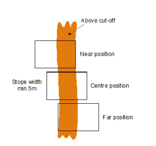
Maximum and minimum footwall/hanging wall change
Enter the distances for both near and far. Reference the diagram below.
Related Topics
Section Method Slice Definition
Section Method Post Processing

