Slice Method: Post Processing
Requirements
A block model must be selected from the Open Specification page.
Instructions
On the Underground menu, point to Analyse, click Stope Optimiser, then select Slice Method > Post-Processing from the tree menu on the left.
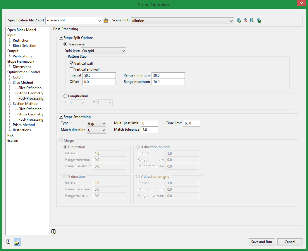
Stope Split Options
This post-processing method will split optimised stopes into smaller sizes based on directions and criteria specify.
Transverse
Transverse will split stopes along the calculated dimension. For example, if you have an XZ stope orientation plane selected, this will split in the Y direction.
Split types:
On grid
Split on a regular stope-framework grid to create a checkerboard pattern (for abutting open stoping layouts).
On grid annealing
Split on a regular stope-framework grid with annealing to create a checkerboard pattern (for abutting open stoping layouts).
Equal
Split equally.
From hanging wall side
Split from hanging wall with the final split adjusted to tolerance settings.
From footwall side
Split from footwall with the final split adjusted to tolerance settings.
From centre
Split from a centred stope. It places the first stope central to the transverse width i.e. not on either side of the centre. The "centre" is defined as being at the mid-stope height).
From far side
Split from far wall with the final split adjusted to tolerance settings.
From near side
Split from the near wall with the final split adjusted to tolerance settings.
Interval
This is the unit used to split the stope.
For example, if the stope was 100 ft in the transverse direction and an interval of 20 was specified, the 100 ft stope would be split into 5 smaller stopes.
Offset
Specify an offset from the start of a stope where to begin the split process.
Range minimum
Minimum size the split stope can have in the specified direction.
Range maximum
Maximum size the split stope can have in the specified direction.
Longitudinal
You can select a number to divide up the stopes in the U and V directions. This will split the stope into equal parts based on the number specified.
Stope smoothing
Select smoothing parameters which will adjust stopes next to one another to ensure a smoother transition from one stope to the next.
Type
Smooth use one of two methods:
Gap
Identifies gaps between the corners of adjacent stopes. In most situations there will only be one stope shape adjacent to the next along strike or up/down dip. If there is a bifurcation in the ore body, then two narrow stopes may be adjacent to one wide stope with a pillar in between the narrow stopes. The Gap method will then maintain the minimum pillar separation between the narrow stopes, and 'snap' the corners of the wide stope with the outside corners of the narrow stopes. If there are stope shapes adjacent to sub shapes, then the stope can be smoothed with the adjacent sub stope, but sub stopes adjacent to each other are not smoothed, In this implementation, only those stope and sub stope corners defined on the stope grid for regular frameworks, or quadrilateral corners for irregular frameworks, will be smoothed.
Ratio
Works by minimizing the Ratio of adjacent stope edges. It requires that only one stope can be adjacent to another and attempts to force the ratio of the side lengths to one equal length. It is only applicable to simple stope configurations.
Multi-pass limit
The number of additional passes through the stope shapes that is allowed to progressively improve the smoothing. The initial pass will often produce excellent results.
Time limit
A time limit (in minutes) for additional smoothing passes.
Match direction
The direction in which stope smoothing is to be applied. The three options are: U, V or UV.
Match tolerance
The maximum gap between adjacent stoping unit (and stoping sub-unit) corners that will be considered for stope smoothing.
Merge
The merging option is similar in concept to splitting stopes, but it performs the opposite function; it merges stope shapes based on provided criteria. There are two options:
U / V direction
Controls merging stopes in the longitudinal direction to a defined interval taking into account the start and end of sequences of stopes.
U / V direction on grid
Controls merging stopes in the longitudinal direction on a regular grid spacing applied in common to all sub levels.
Interval
The target length for stopes in the longitudinal direction. The target length should be a multiple of the stoping unit dimension.
Range minimum
The minimum length for stopes in the longitudinal direction. This length should be a multiple of the stoping unit dimension.
Range maximum
The maximum length for stopes in the longitudinal direction. This length should be a multiple of the stoping unit dimension.
Related Topics
Section Method Slice Definition
Section Method Post Processing

