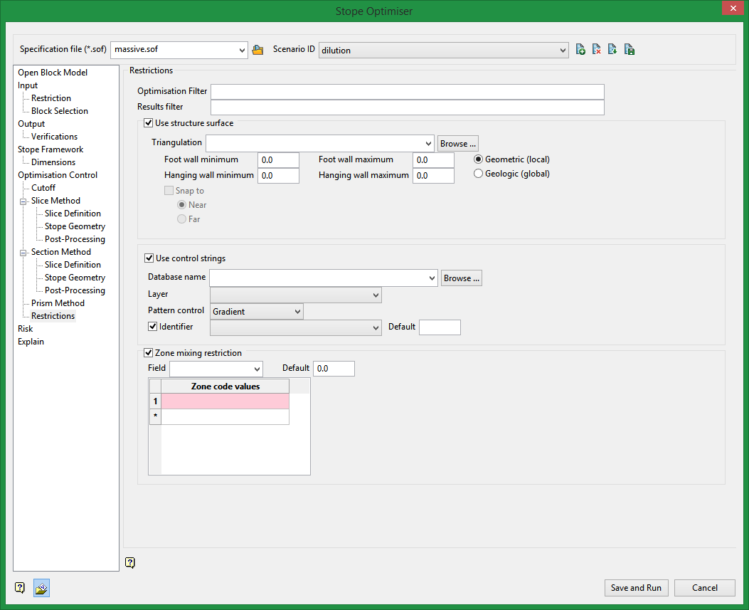
Restrictions
Use Restrictions to control the shapes and positions of stopes by restricting selected parameters.
Requirements
A block model must be selected from the Open Specification page.
Instructions
On the Underground menu, point to Analyse, click Stope Optimiser, and then select Restrictions from the tree menu on the left to display the Restrictions pane.

Filters
Use condition statements to add filters for the output stopes.
An example: cu GT 1.5 and au GT 0.5
These conditions must be met in addition to the cutoff parameters and physical constraints specified elsewhere in the option.
Use structure surface
Specify a triangulation that represents a structure surface. Output stopes will extend out to this surface and break to it if the stope is withing a nominated distance of the specified triangulation.
Use control strings
You can specify a layer from a DGD that contains strings. These strings, along with a specified method, will control the shape and position of stopes.
For example, you may have a set of inclined strings that represent desired level positions and orientations. If you select the gradient method for pattern control these strings will be used to force the stope levels to follow the input strings.
Zone mixing restriction
Select this option to restrict the occurrence of multiple code values for a field in a stoping unit. You will need to specify an block model variable and a set of zone code values. Stopes can be formed for any individual code value, but not a mixture. If different lenses have different ore types and stopes, you cannot mix the ore types.
Related Topics
Section Method Slice Definition
Section Method Post Processing

