Slice Method
Slice Method provides analysis of unit and stope orientation for specifying how it will slice through a mode. Slices that meet optimal criteria are annealed together into stope shapes.
Three different stope shapes are recognised:
- Full shapes, the framework cell dimension in U and V
- Sub-shapes, a regular or irregular interval of the full shape
- Development dimensions, with a width and height
In the stope optimisation run, full shapes are processed first, and then sub-shapes of the remaining ore not mined with a full shape, and lastly development shapes of the ore that cannot be taken in full shapes or sub-shapes.
Sub-shapes are defined either with fixed dimension by specifying the number of sub-shapes in the U and V axis, an automatically generated list of sub-shapes, or alternatively by specifying a user defined list of shapes. The last enables irregular shapes to be defined (for example the stope and drive shapes, or the primary and secondary stope shapes) and would be used without full shapes being specified. A number of automatic configurations of sub-shapes can be supplied where the interval dimension is given on the U or the V axis (but not both), and where sub-shapes abut the framework cell boundary, and the largest sub-shape is chosen first. These automatic methods have the goal of identifying how stope sub-shapes might be used to find a sub-shape contiguous with an adjacent full shape (or sub-shape).
By default sub-shapes are processed in the order supplied (either from a user supplied list or an automatically generated list), and ore will be mined in the first economic sub-shape. In the case where there are multiple lenses and potentially multiple stopes transversely across strike, if one lens is successful with a full stope, but not the others, the others will still be considered for sub-stopes.
Requirements
A block model must be selected from the Open Specification page.
Instructions
On the Underground menu, point to Analyse, click Stope Optimiser, and then select Slice Method from the tree menu on the left to display the Slice Method panel.
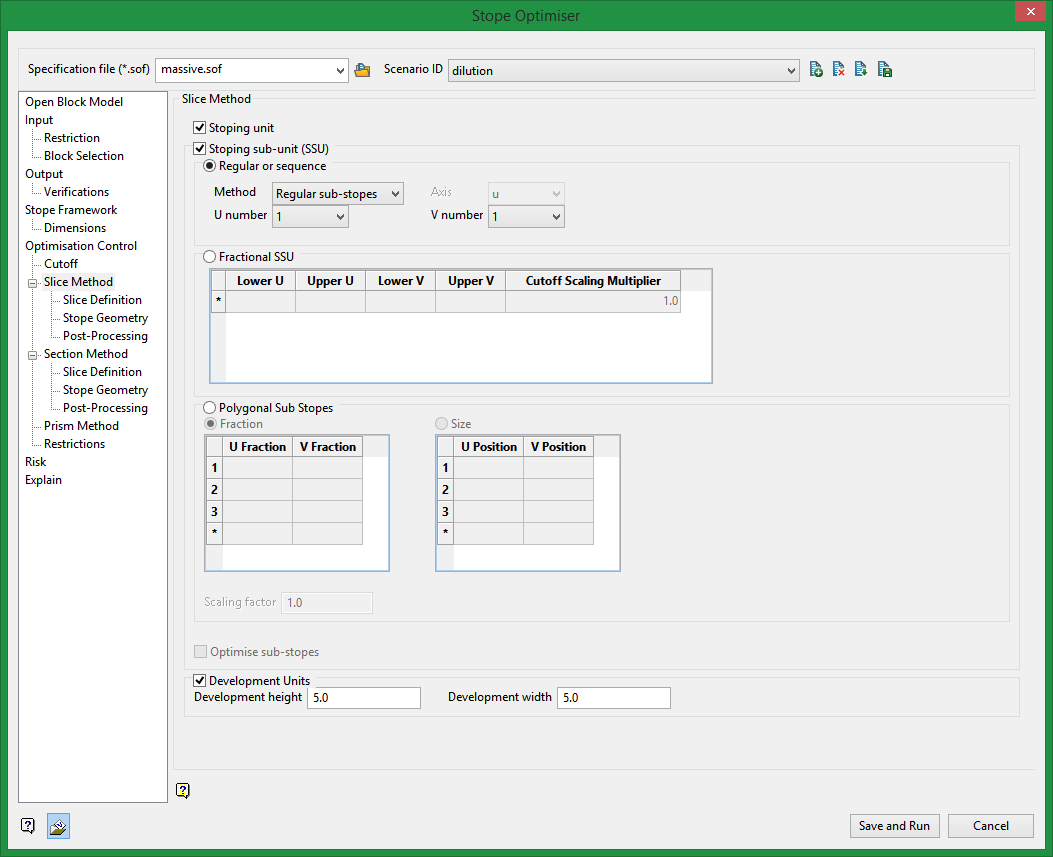
Slice Method
Stoping unit
Refers back to what was used on the stope framework panel.
Stoping sub-unit (SSU)
By default sub-units are processed in the order supplied (either from a user supplied list or an automatically generated list), and ore will be mined in the first economic sub-shape. In the case where there are multiple lenses and potentially multiple stopes transversely across strike, if one lens is successful with a full stope, but not the others, the others will still be considered for sub-stopes.
If the option to optimise sub-stopes is selected, then an optimal choice of sub-shapes is made to maximise the value (or metal).
Note: The stope optimiser does not check the combination of full stopes and sub-stopes simultaneously and give the one that optimises grade/value/calculated value. In other words, if a solution exists with a full shape and another solution exists with a sub shape(s) and the sub shape solution has a higher grade and the user is maximising grade, the full shape will still be generated.
Also, if there are multiple lenses and multiple stopes transversely across strike, the lenses are not checked simultaneously for the choice of full stope and sub-stope combinations – the full stope shape is applied to all lenses, and where a full stope does not create an economic stope, a substope will be considered.
When using a stoping sub-unit there are three main methods: Regular or sequence, Fractional SSU, and Polygonal Sub Stopes.
Regular or sequence
Within the Regular or sequence methods are additional sub-methods: Regular, edge, back, forward
For any of the methods in Regular or sequence you must specify an axis and then a stoping sub-unit number for that axis. This number will determine how full size stopes may be reduced to a stoping sub-unit.
Example: In an XZ stope orientation plane with an X step of 20 and a Z step of 60, a full size stope will be 20 x 60. Specifying a stoping sub-unit with Axis V and a V number of 3, the stoping sub-unit will be 20 in the Z direction. This would result in stopes that are 20 x 20.
Fractional SSU
For the Fractional SSU you can specify fractions to determine stope sizes and locations for the stoping sub-unit.
To set up a design with a primary/secondary stoping sequence with 20 ft primaries and 40 ft secondaries, and all stopes 60 ft high. With a stope orientation plane of XZ with an X step of 60 and a Z step of 60, the fractional SSU would be:
This would split up the X step into 20 and 40.
Polygonal Sub Stopes
For sub-stope polygons a closed string is supplied to define a non-rectangular shape. A smaller model discretisation interval should be considered for more accurate approximate stope evaluation, or else the exact evaluation method should be used.
Fraction
Specify the fractions that will determine the stope sizes for both the U and V axes. Enter values between 0.0 and 1.0.
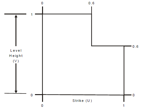
Size
Specify the polygon U and V position.
Scaling factor
Scaling factor to be applied to the cutoff for an irregular stoping sub-unit.
Optimise sub-stopes
Optimisation evaluates all sub-stopes and finds the best combination of non-overlapping sub-stopes. The processing time overhead should not be any higher than evaluating the list of sub-stopes. If you evaluate a list of overlapping stopes on parallel lenses (without optimisation) you might get overlapping stope shapes from one lens to the next and also potentially get a higher value. If you optimise, you are selecting a set of non-overlapping sub-stopes, and these are the only shapes that will be used on each lens. If you don't use sub-stope optimisation, then each shape in the list is run in turn, and any lens that can form stopes from that shape will do so at the first opportunity. In the optimise case it looks for the best overall solution with a subset of the shapes, whereas in the non-optimise case it applies a sub-stope at the first available opportunity, and consequently the sub-stopes from one lens might overlap the sub-stopes from another adjacent lens (which cannot occur by definition in the optimise case).
If a full stope shape is included in the sub-shape list then optimisation can assess whether a substope captures more value than a full stope that is otherwise forced to mine more included waste.
In the case where there are multiple lenses and potentially multiple stopes transversely across strike, if one lens is successful with a full stope, but not the others, then the others still be considered for sub-stopes.
Development Units
Specify height and width dimensions for a tertiary type sub-stope.
Related Topics
Section Method Slice Definition
Section Method Post Processing

