Slice Method: Stope Geometry
Use Slice Method Stope Geometry to define the physical constraints of the stope. These measurements can be based on ground conditions and/or on equipment.
Requirements
A block model must be selected from the Open Specification page.
Instructions
On the Underground menu, point to Analyse, click Stope Optimiser, and then select Slice Method > Stope Geometry from the tree menu on the left to display the Stope Geometry panel. If you have selected an XZ or YZ stope orientation plane you will get the Vertical Stope Geometry panel. If you have selected XY or YX then you will get the Horizontal Stope Geometry panel
Horizontal Stope Geometry
Minimum stope height
Enter the minimum mining height (>/= 0.0) allowed for this stope shape. The default is 5.0.
Maximum stope height
Enter the maximum mining height allowed for this stope shape. The value must be greater than the defined minimum. The default is 100.0
Minimum waste pillar height
Enter the minimum waste pillar height (>/= 0.0). A waste pillar is inserted once the maximum stope width/length has been met. It inserts the pillar in-between adjacent stopes in the calculated direction. If you mine up against fill and do not require a waste pillar you can put in a small number (0.01 for example). The optimizer does not support a zero value for waste pillar height.
Strike Dip
Minimum
Enter the minimum allowable strike angle of the stope. This strike angle is applied to edge on the calculated axis of the stope. The default is -45.00.
Maximum
Enter the maximum allowable strike angle of the stope. This strike angle is applied to the edge on the calculated axis of the stope. The default is 20.0.
Maximum change
Enter the maximum difference in angle in degrees (0.0 - 90.0) between the top and bottom edges of the side of a stope shape. The default is 20.0.
Transverse Dip
Minimum floor
The minimum transverse dip angle for the floor (different roof/floor method)
Maximum floor change
The maximum difference in angle in degrees between the front and back transverse dip angles on the floor (different roof/floor method)
Maximum floor
The maximum transverse dip angle for the floor (different roof/floor method)
Minimum roof
The minimum transverse dip angle for the roof (different roof/floor method)
Maximum roof change
The maximum difference in angle in degrees between the front and back transverse dip angles on the roof (different roof/floor method)
Maximum roof
The maximum transverse dip angle for the roof (different roof/floor method)
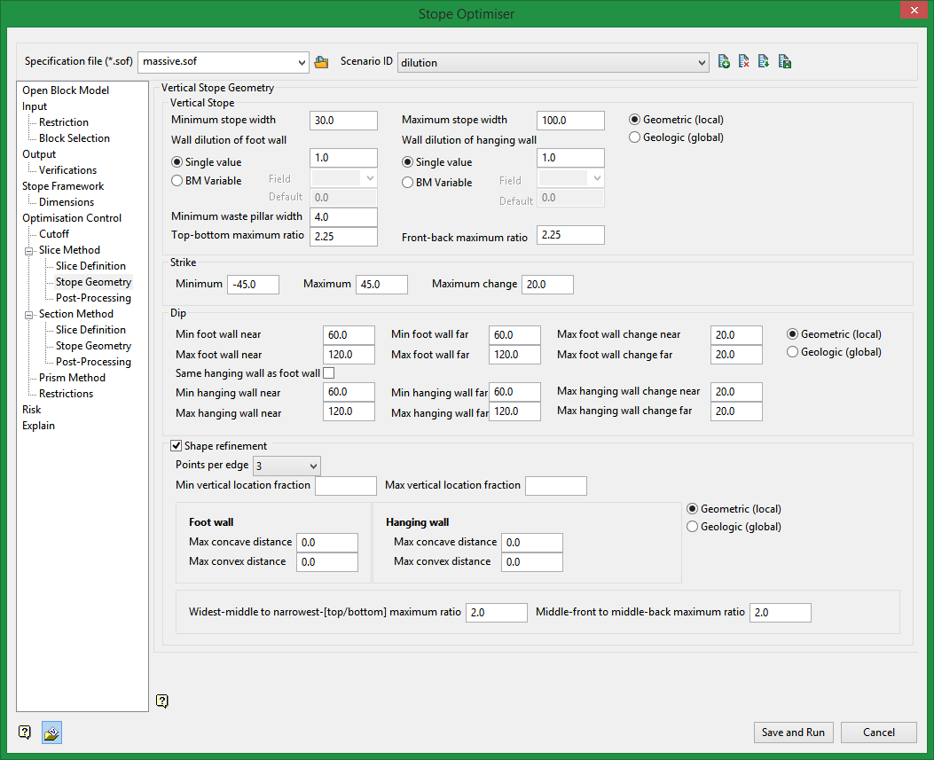
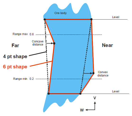
Shape refinement
The position of the additional points is defined relative to the original 4 points. The position is defined by a vertical range, as shown in the diagram, where a range fraction of 0.2-0.8 is depicted.
Points per edge
The number of points is specified by defining the number of points on each wall, being either 2, 3 or 4 points.
Min vertical location fraction
Enter a value for the minimum vertical location of the mid-point/s n on the footwall side. The default is 0.5.
Max vertical location fraction
Enter a value for the maximum vertical location of the mid-point/s n on the footwall side. This value must be greater than the minimum value. The default is 0.5.
Floor / Roof
The lateral position of the points can be constrained relative to a line joining the stope corners (see dotted lines). The lateral position can be constrained to an outwards limit (the convex distance), and/or to an inwards limit (the concave distance). In this way each wall (near, far, hangingwall or footwall) can be constrained to be either concave only, convex only, or any position in between a convex/concave limit.
Max concave distance
Maximum distance allowed in the concave direction on the footwall side. The default is 0.0.
Max convex distance
Maximum distance allowed in the convex direction on the footwall side. The default is 0.0.
Middle to top/bottom ratio
The upper limit for the ratio (longer/shorter) of the middle edges of the top and bottom face of a stope shape. Enter a value equal to or greater than 1.0. The default is 1.20.
Left to right ratio
The upper limit for the ratio (longer/shorter) of the middle edges of the front and back face of a stope shape. Enter a value equal to or greater than 1.0. The default is 1.20.
Trough Undercut
Width
The width of the trough undercut at the floor of the stope. The default is 5.0.
Angle
Trough undercut angle. The default is 50.0.
Position
The relative position of the trough to the stope. The default is centre.
Min
The minimum depth of the trough undercut. The default is 0.0.
Max
The maximum depth of the trough undercut. The default is 0.0.
Step
The increment that is used for determining the width of the trough. It should be in sub-multiples if the difference between min and max.
Related Topics
Section Method Slice Definition
Section Method Post Processing

