Slice Method: Slice Definition
Use Slice Definition to define the dip, strike and interval default values for the stope slice. These will be used by the optimiser's algorithm to determine valid stope shapes.
Requirements
A block model must be selected from the Open Specification page.
Instructions
On the Underground menu, point to Analyse, click Stope Optimiser, and then select Slice Method > Slice Definition from the tree menu on the left to display the Slice Definition panel.
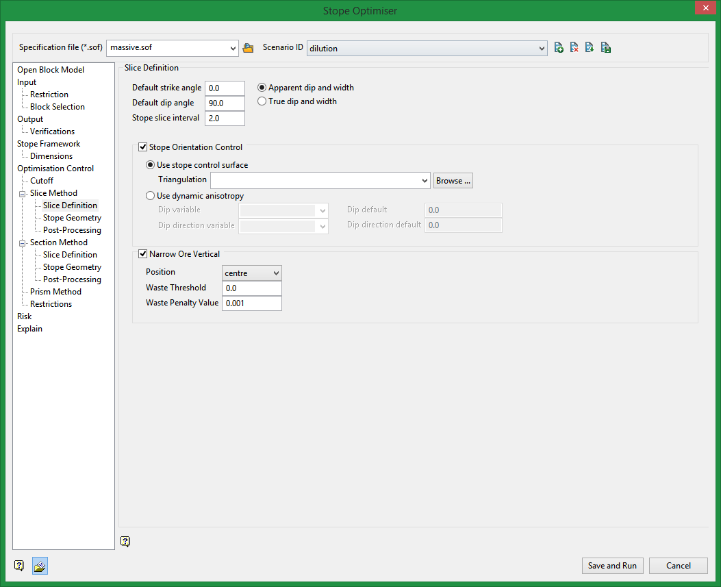
Slice Definition
Default strike dip angle
Enter the desired strike value (0 - 90) to be used as the default. Standard default by the Stope Optimisation convention is 0.0.
Default transverse dip angle
Enter the desired dip value (0 - 180) to be used as the default. 0.0 is to the left looking along the strike, and 90.0 is looking vertically down. Standard default by the Stope Optimisation convention is 90.0.
|
Values |
Default |
|
|---|---|---|
|
Apparent dip |
0.0 to 180.0 |
90.0 |
|
Apparent strike |
-90.0 to 90.0 |
0.0 |
|
True dip |
0.0 to 90.0 |
90.0 |
|
True strike |
0.0 to 360.0 |
0.0 |
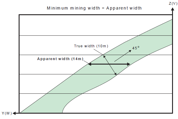
Apparent dip and width vs. True dip and width
Stope slice interval
Enter the desired slice thickness for the slices in an amount greater than 0.0. The standard default is 1.0.
Stope Orientation Control
Select this check box to enable the mineable shape definition/bounding options.
Stope Orientation Control
Select one of the following:
Use stope control surface
Select this option to use a triangulation to provide localized strike and dip values for the slicing unit.
Use dynamic anisotropy
Select this option to define localized strike and dip values by provided a block model variables containing strike and dip values.
The block model needs these two additional numeric fields to define the stope orientation at the cell centre. In most cases the orebody orientation, derived from hanging wall and footwall surfaces, will be a proxy for the stope orientation.
Dip variable
Select from the drop-down list the variable from the block model which contains localized strike values. Variables available from the currently loaded block model are listed.
You will also need to define a Default in angle in degrees (0.0 - 190.0) that will be used when the model cells do not fill the framework space, or a grade field is not defined.
Dip direction variable
Select from the drop-down list the variable from the block model which contains localized dip values.
You will also need to define a Default in degrees (0.0 - 90.0) that will be used when the model cells do not fill the framework space, or a grade field is not defined.
Narrow Ore Horizontal
Position
Select the relative location of ore within a stope.
Waste Threshold
Specify the minimum value of material below cutoff that will be included in the calculation of the ore position.
Waste Penalty Value
Material falling below this value will be considered as waste. The default value is 0.001.
Related Topics
Section Method Slice Definition
Section Method Post Processing

