Grid
The Grid tool (Create tab > Create group) allows you to fit a grid pattern to a surface. You can generate a regular grid pattern either as points ![]() , which can be useful for indicating spot heights, or as lines
, which can be useful for indicating spot heights, or as lines ![]() , which can provide a simplified representation of a surface.
, which can provide a simplified representation of a surface.
To create a grid, follow these steps:
-
On the Create tab, in the Create group, click
 Grid.
Grid.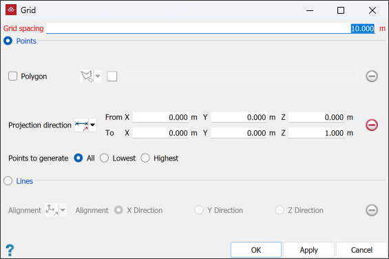
-
Enter a Grid spacing appropriate to the data.
-
Select the required grid type as Points or Lines.
 Expand if you selected Points
-
To restrict the grid to a specific area, select Polygon and define a polygon around that area. You can draw a polygon for this tool in either of the following two ways:
-
Select
 By Polygon, then drag a polygon into the Polygon field.
Note: If a suitable polygon does not exist, create one with the
 Polygon tool. See Lines and Polygons.
 -
Select
 By Points, then create a polygon by selecting points in the view window or entering coordinates in the Grid tool panel. Complete the polygon by clicking Apply or OK.
If you leave Polygon unselected, the grid will cover the entire object.
-
-
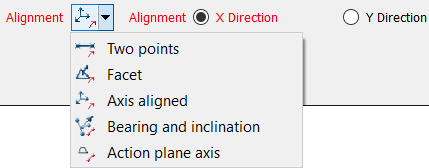
Adjust the orientation of the grid with the most suitable Projection direction option.

Two points
Define the direction by specifying two points.

Facet
Make the direction perpendicular to a selected facet.

Axis aligned
Define the direction by an axis of the view window.

Bearing and inclination
Define the direction by a bearing and inclination angles.

Action plane axis
Define the direction by an axis of the action plane.

Polygon best-fit plane normal
Define the direction as the normal to a plane-of-best-fit to a polygon.
-
Select which Points to generate in the grid from All points fitted to the surface, the Lowest points, or the Highest points.
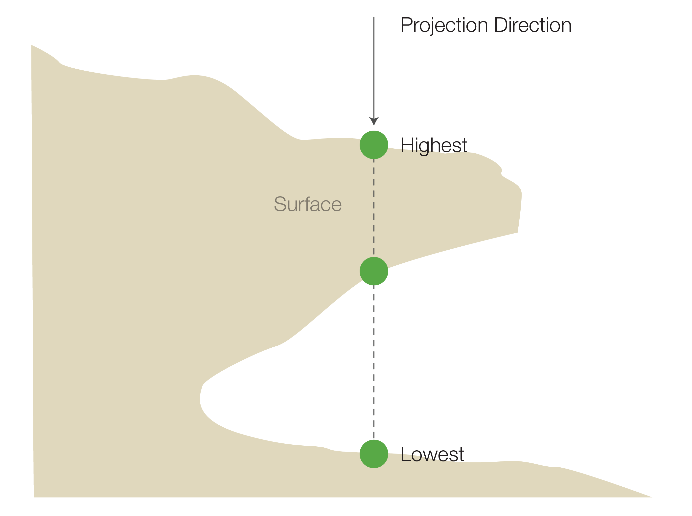
A representation of points that would be selected with overhanging data, depending on the chosen Points to generate option. Selecting All will generate all points in the projection direction.
-
Select the surface to be fitted with the grid.
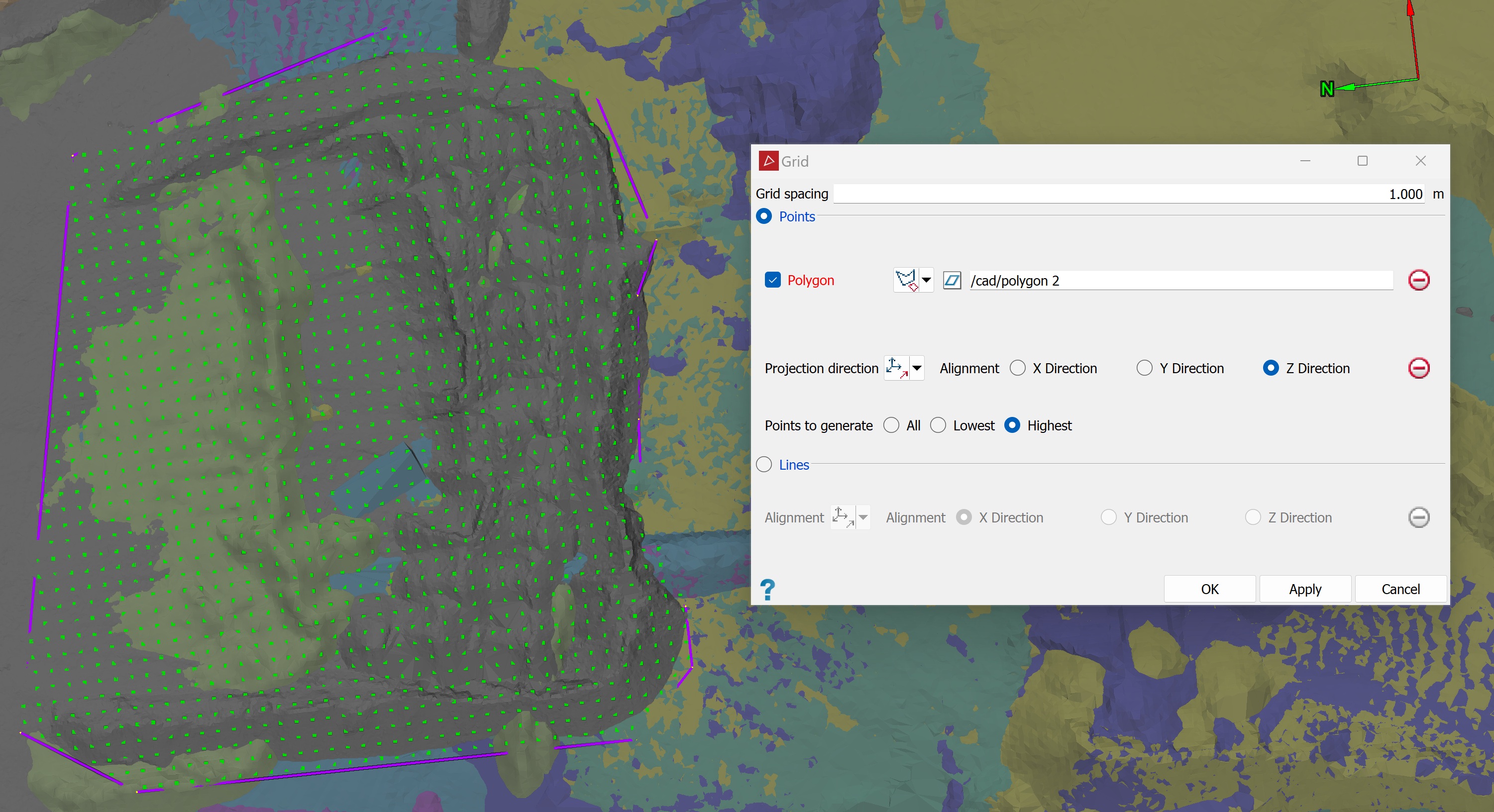
A horizontal grid of points bounded by a polygon.
Expand if you selected Lines
Adjust the orientation of the grid lines with the most suitable Alignment option.
Two points
Define the direction by specifying two points.
Facet
Make the direction perpendicular to a selected facet.
Axis aligned
Define the direction by an axis of the view window.
Bearing and inclination
Define the direction by a bearing and inclination angles.
Action plane axis
Define the direction by an axis of the action plane.
Note: Only the X and Y components are used in creating the grid. The grid is always projected in the Z direction. If no X or Y alignment is provided, the grid will automatically align with the axes.
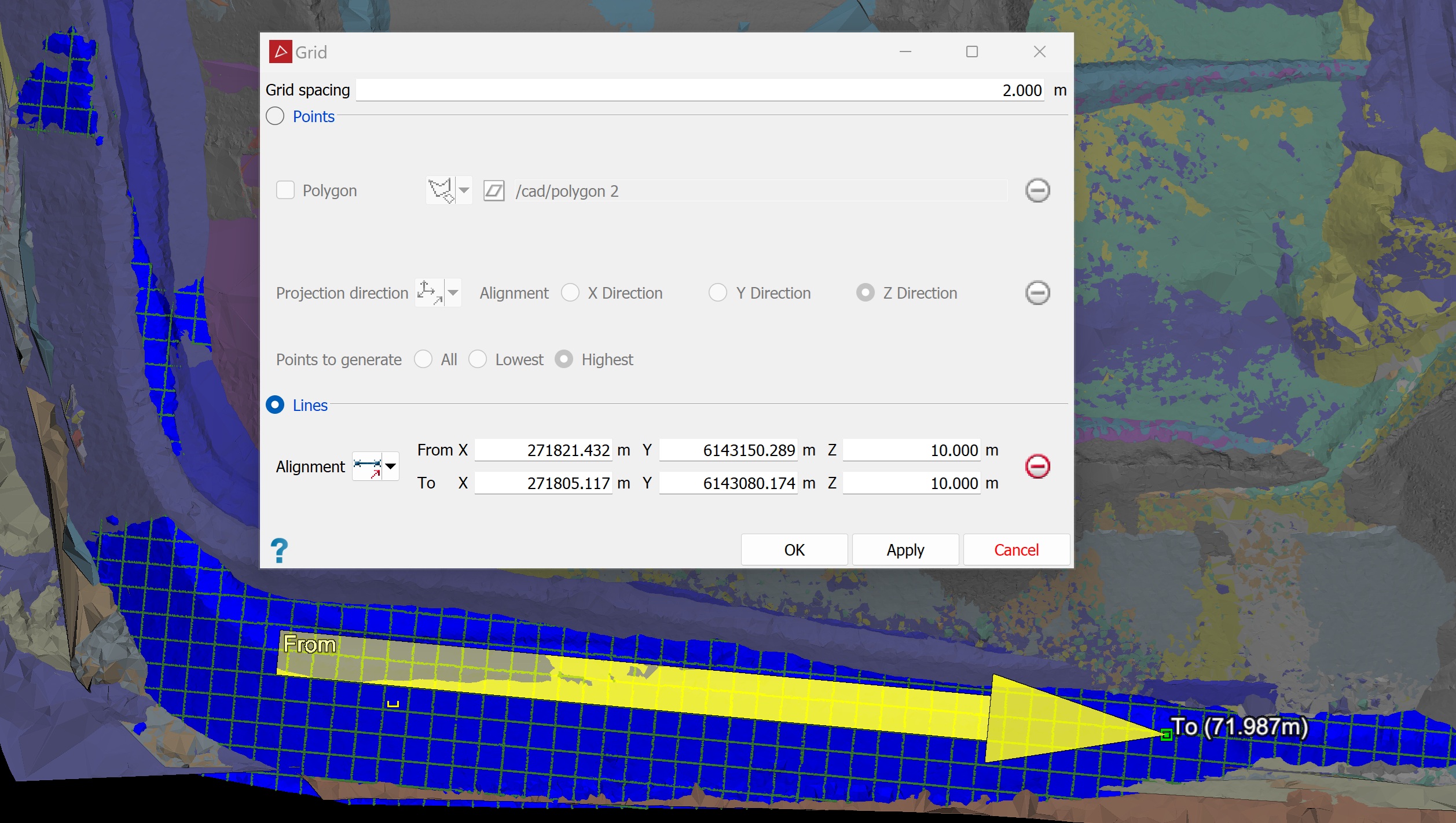
A grid created as lines applied to a selected surface. The alignment vector disappears when the tool is closed.
-
-
Click OK or Apply.
The grid is
saved in the ![]()
cad container.
