View Window Toolbar
Source file: view-window-toolbar.htm

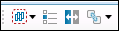
The view window toolbar allows you to modify the display of data in the view window. It consists of three menu groups: View Operations, Action Plane, and Visibility Editor.
View Operations

| Icon | Label | Description |
|---|---|---|
|
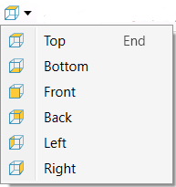
Predefined Views |
Displays the data from a fixed direction. Tip: Click this icon to reset the view so all data is visible. |

|
Set View Point | Prompts you to set the position and orientation of the camera. |

|
Centre of Rotation | When rotating a view, the centre of rotation is at the position of the axes in the view window. You can change the centre of rotation by clicking on the button in the view window toolbar and then clicking at the desired new location for the axes.
|
|
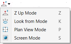
Manipulation Mode |
|

|
Projection Mode | Toggles between Orthographic and Perspective projection.
Perspective projection displays data as it would appear if you were looking at it, showing distant objects as smaller. Orthographic projection displays all data at the same size regardless of distance from the camera. |

|
Zoom to Selection | Zooms into selection. |

|
Select All | Selects everything in the view. |

|
Invert selection | Selects everything in the view that has not been selected and clears what was previously selected. |

|
Image render | Allows a screen capture of the view window. For more information, see Image Render. |
|
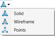
Surface render mode | Toggles the display of data between Note: The |
|
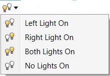
Side light | Changes the headlight direction to alter the display of shadows. |

|
Headlight | Turns the headlights on and off. |

|
Dimension | Toggles the view between 2D and 3D mode. |

|
Label | Turns the hole labels on or off. |
|
|
Hole length | Turns the hole length display on or off. |
|
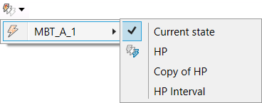
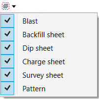
Snapshots | Displays the snapshots of the blast in the view window. You can also switch between the snapshots in the view window by selecting the desired snapshot from the drop-down menu. For more information on snapshots, see Create Snapshot. |
|
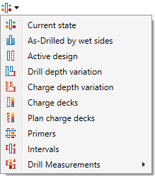
Visualisation | Contains options to change the visualisation of information about the holes in the view window. For more information on this tool, see Visualisation. |

|
Coordinate grid on | Turns the coordinate grid on and off. |

|
Profile | Enables easy visualisation of a single row or echelon of holes with only the relevant data visible in the view. This tool is used to easily modify hole charge plans and intervals by directly manipulating them. Direct manipulation allows fine tuning of intervals and charge plans more closely to relevant measurements such as accurate coal surfaces and hole water measurements. For information on how to use this tool, see Profile View. |

|
2D Hole view | Displays a two dimensional view of the hole including planned charge products. |

|
Find hole |
Use
Tip: You can also use the |
Action Plane
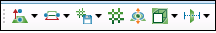
| Icon | Label | Description |
|---|---|---|
|
Set | Set action plane toolbar |
|
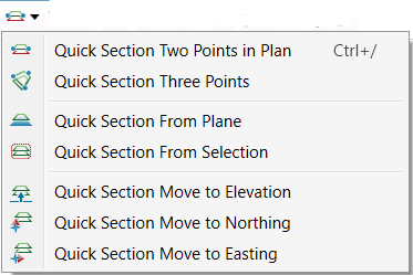
Quick section | |
|
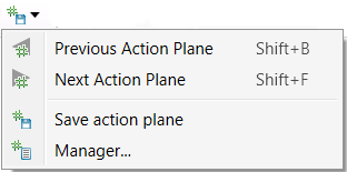
Save planes | |

|
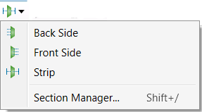
Action plane visibility | The action plane toolbar is used to control the action plane in the view window. |

|
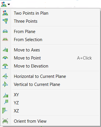
Action plane manipulator | |
|
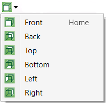
Action plane predefined views | |
|
Section mode | Enables you to load multiple objects and surfaces into the view, and step by step view in detail relative positions and potential interactions. For more information on this tool, see Section Mode. |
Visibility Editor

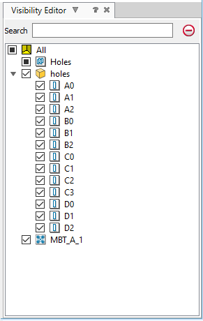

See also: Viewing Objects
