Surfaces
Source file: surfaces.htm
The Surface group of the Geometry tab contains tools that allow you to generate surfaces from different data sources.
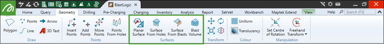
Surface generation allows you to visualise discrepancies in a dataset for a single variable. You can generate surfaces from both hole and blast data. BlastLogic saves the generated surfaces to the cad container that is located in the project explorer.
Planar Surface
Use ![]() Planar Surface to create triangulation surfaces from any data containing more than three points. This function works in any defined plane, so that vertical or subvertical data, such as fault planes, can be modelled.
Planar Surface to create triangulation surfaces from any data containing more than three points. This function works in any defined plane, so that vertical or subvertical data, such as fault planes, can be modelled.
To use this tool:
-
Go to Geometry tab > Surface group >
 Planar Surface. This will open a new panel.
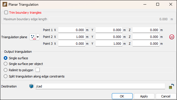
-
Select the Trim boundary triangles checkbox to eliminate long, incorrectly generated boundary triangles. When selected, specifying a maximum boundary edge length prevents triangles greater than this being created.
Note: This option is only applicable to boundary triangles; large voids in the centre of the data will still be modelled assuming they are enclosed by smaller triangles.
-
Define the orientation for the triangulation plane so that it is aligned subparallel to the data. You can change the input geometry by selecting the Triangulation plane from the drop-down list.
 Three points
Select three point coordinates to define a plane.
 Point and normal
Select a point for the plane centre, then select a second point for the plane to be normal to.
 Point and orientation
Select a point coordinate to define the location of the plane. The plane will be relative to the view orientation.
 Facet and offset
Select a facet on a triangulation by clicking in the view window, then enter an offset distance. The direction will be normal to the facet.
 Point, strike and dip
Select a point coordinate, then define a dip (-90 to 90 degrees) and strike (0-360 degrees).
 Axis aligned
Select a point coordinate, then select an axis (x, y, z).
 Action Plane
Automatically chooses the action plane of active view.
-
Specify an option under Output triangulation to define what objects are to be created:
-
Single surface creates a single triangulation from the selection.
-
Single surface per object creates separate triangulations for each selected object. Surfaces generated by this method are stored in the surfaces container and named according to the parent object.
-
Relimit to polygon constrains the model to a polygon, for example a tenement boundary.
-
Split triangulation along edge constraints splits the triangulation into separate objects based on any lines or polygons selected in the explorer window when the triangulation is created.
-
-
Ensure the data to be triangulated is selected in the explorer window or view window and click OK or Apply.
The triangulation is saved in thecadcontainer by default.
Surface From Holes
The ![]() Surface From Holes tool allows you to generate a surface from a selection of holes.
Surface From Holes tool allows you to generate a surface from a selection of holes.
To generate a surface from a selection of holes, follow these steps:
-
Select the required holes in the view window or project explorer.
-
On the Geometry tab, in the Surfaces group, select
 Surface From Holes.
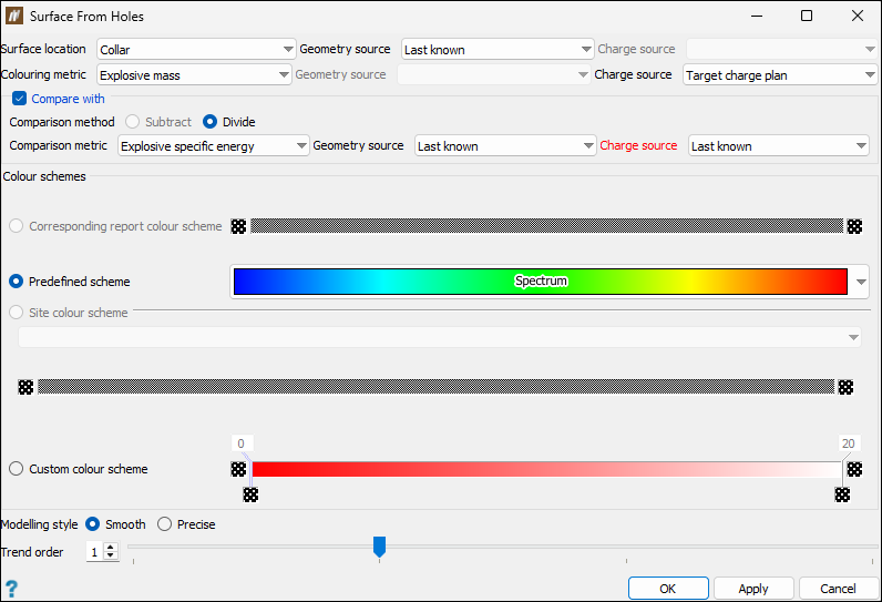
 The Surface From Holes panel will appear.
-
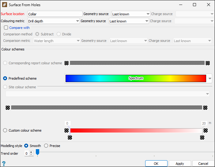
Configure the surface to be generated by setting the following fields:
-
Surface location. The surface location defines the z-value at which the surface appears. A hole dataset, which has similar surface location values, will appear relatively flat, whereas a surface with significantly different surface location values will have an uneven surface.
Select the required surface location from the drop-down. You can select from the following:
-
Collar
-
Toe
-
Charge depth
-
Water
-
Wet sides
-
Lowest explosive deck bottom
-
Custom hole properties of float type that you have defined in the Hole properties tab (Home tab > Setup group >
 Site). For more information, see Hole properties.
Depending on the chosen surface location, either the Geometry source or Charge source drop-down will be enabled.
Note: The Geometry source and Charge source drop-downs will both be disabled if you have selected a custom hole property as the surface location.
Specify the source as follows:
-
For Geometry source, select one of the following:
-
Last known
-
Reference design
-
Survey
-
Drilling
-
Design
-
-
For Charge source, select one of the following:
-
Last known
-
Reference design
-
Reconciled
-
Loaded
-
Charge plan
-
Target charge plan
-
-
-
Colouring metric. The colouring metric is a variable that sets how BlastLogic will colour the surface. For example, say you set the colouring metric to variable X, where X is a shared attribute amongst a selection of holes. The following outcomes can occur:
-
If there is great variation in X between the holes, then the surface will be varied in colour.
-
If there is little variation in X between the holes, then the surface will have fewer colours.
Select the required colouring metric from the drop-down. You can select one property from the listed hole built-in locations, metrics, and custom properties of float type.
Depending on the chosen colouring metric, either the Geometry source or Charge source drop-down will be enabled.
Note: The Geometry source and Charge source drop-downs will be disabled if you have selected a custom hole property as the colouring metric.
Specify the source by selecting the required option from the enabled drop-down. The options listed for each source are the same as for the surface location (see surface location sources for more information).
-
-
-
Optionally, select the Compare with checkbox.
In this section, you can set the following:
-
Comparison method by selecting either the Subtract or Divide radio button.
Note: The available comparison methods will depend on the surface location and colouring metric that you have selected in the previous step.
-
Comparison metric, Geometry source, and Charge source by selecting the required option from the drop-down.
Note: The options listed for Geometry source and Charge source are the same as for the surface location (see surface location sources for more information).
-
-
Select the radio button of the desired colour scheme in the Colour schemes section. You can choose from the following colour schemes:
-
Corresponding report colour scheme
This option is only available for colour metrics previously set in the Report setup tab of the Site setup panel (Home > Setup >
Site). For more information on setting report colours, see the Report setup section of the Setup page. -
Predefined scheme
This option allows you to select from predefined colour schemes stored in BlastLogic. Select the required scheme from the Spectrum drop-down.
-
Site colour scheme
This option allows you to select from colour schemes you (or other users) have previously defined. You can define these schemes in the custom colour schemes tab of the Site Setup panel tool (Home > Setup >
Site). See the Custom colour schemes section of the Setup group for information on creating custom colour schemes.Note: The site colouring scheme should have the same units as the selected colouring metric.
-
Custom colour scheme
This option allows you to design a new custom colour scheme. To do this, follow these steps:-
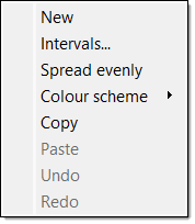
Right-click on the colour band. The following context menu will appear.
-
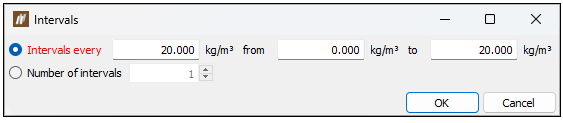
Select Intervals.... The Intervals panel will appear.
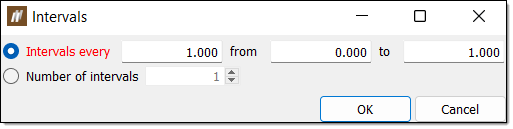
-
Select either Intervals every or Number of intervals using the corresponding radio buttons.
-
Enter the desired intervals.
-
For Intervals every, enter the space between intervals along with the starting and end points in the associated fields.
-
For Number of intervals, enter the number of intervals in the associated field.
-
-
Click OK.
 Expand for an alternative boundary setting method.
You can also use the following method to set additional boundaries:
-
Move the mouse to the edge of the colour band such that the cursor changes to a horizontal resize cursor and click.
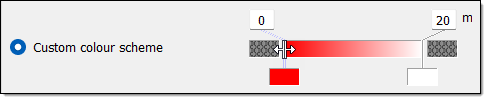
-
Drag the cursor to the desired boundary position. Continue this process until you have defined the necessary boundaries.
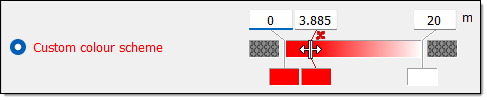
Tip: Click
 above a boundary to delete it.
-
-
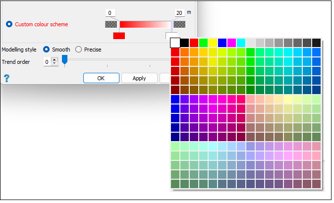
Set the boundary colours. You can do this in either of the following ways:
-
Right-click on the colour band and hover over the Colour scheme option in the context menu. Select the desired colour scheme from the list.
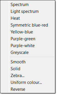
-
Select the colour block corresponding to a boundary and select the desired colour from the colour palette.
-
-
-
-
Select the appropriate modelling style via the Modelling style radio buttons. There are two modelling styles to select from:
-
Smooth
The smooth modelling style creates a surface using interpolated data. In this case, you can also alter the trend order using the Trend order slider as required. This trend defines the extent of approximating that BlastLogic will perform. The greater the trend order, the smoother the surface.
-
Precise
The precise modelling style creates a surface at the exact points without any approximations. In this case, you can also select the Manual maximum edge length checkbox and enter a length in the Length field.
In general, BlastLogic generates a surface from a collection of triangulations using an algorithm. This algorithm treats triangulations at the edge of the surface as outliers and removes them to create a more representative object. Triangulations are removed based on their edge length that BlastLogic automatically calculates. However, you can override using the manual maximum edge length. As a result, any triangulation at the boundary with an edge greater than the manual maximum edge length will be removed from further calculations.
-
-
Click OK or Apply.
BlastLogic will save the surface to the
cadcontainer in the project explorer. To view the generated surface with the blast, middle‑click the surface and drag it into your workspace.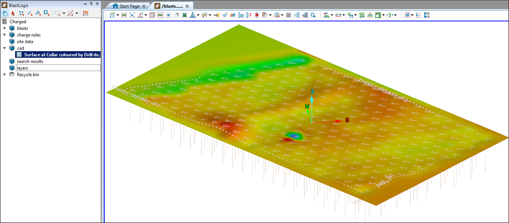
Surface From Blasts
The ![]() Surface From Blasts tool allows you to generate surfaces from a selection of blasts.
Surface From Blasts tool allows you to generate surfaces from a selection of blasts.
To generate a surface from a selection of blasts, follow these steps:
-
Select the desired blasts in the project explorer. BlastLogic will create a surface for each blast you select.
-
On the Geometry tab, in the Surfaces group, select
 Surface From Blasts.
The Surface From Blasts panel will appear.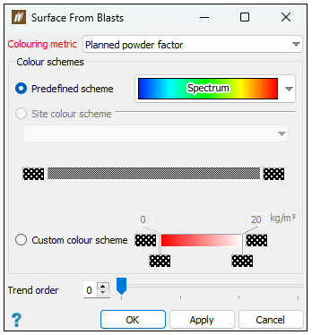
-
Select a colouring variable from the Colouring metric drop-down.
Expand for more information on the colouring metric.
The colouring metric is a variable that sets how BlastLogic will colour the surfaces. For example, if you set the colouring metric to variable X, where X is a shared attribute amongst a selection of blasts, the following outcomes can occur:
-
If there is great variation in X between the blasts, then the resulting surfaces will be varied in colour.
-
If there is little variation in X between the blasts, then the resulting surfaces will have less colour variation.
-
-
Select the radio button of the desired colour scheme in the Colour schemes section. You can choose from the following colour schemes:
-
Predefined scheme
This option allows you to select from premade colour schemes stored in BlastLogic. Select the desired scheme from the Spectrum drop-down. -
Site colour scheme
This option allows you to select from colour schemes you (or other users) have previously defined. You can define these schemes in the custom colour schemes tab of the Site Setup panel tool (Home > Setup >Site). See Custom colour schemes section of the Setup group for information on creating custom colour schemes.Note: The site colouring scheme should have the same units as the selected colouring metric.
-
Custom colour scheme
This option allows you to design a new custom colour scheme. To do this, follow these steps:-
Right-click on the colour band. The following context menu will appear.
-
Select Intervals.... The Intervals panel will appear.
-
Select either Intervals every or Number of intervals using the corresponding radio buttons.
-
Enter the desired intervals.
-
For Intervals every, enter the space between intervals along with the starting and end points in the associated fields.
-
For Number of intervals, enter the number of intervals in the associated field.
-
-
Click OK.
Expand for an alternative boundary setting method.
You can also use the following method to set additional boundaries:
-
Move the mouse to the edge of the colour band such that the cursor changes to a horizontal resize cursor and click.
-
Drag the cursor to the desired boundary position. Continue this process until you have defined the necessary boundaries.
Tip: Click
above a boundary to delete it.
-
-
Set the boundary colours. You can do this in either of the following ways:
-
Right-click on the colour band and hover over the Colour scheme option in the context menu. Select the desired colour scheme from the list.
-
Select the colour block corresponding to a boundary and select the desired colour from the colour palette.
-
-
-
-
Optionally, set the trend order using the Trend order slider. This trend defines the extent of approximating that BlastLogic will perform. The greater the trend order, the smoother the surface.
-
Click OK or Apply. BlastLogic will save the surface to the
cadcontainer in the project explorer.
Blast Volume
To generate a blast volume object, follow these steps:
-
Select the desired holes or blast in the view window or project explorer.
-
On the Geometry tab, in the Surfaces group, select
 Blast Volume.
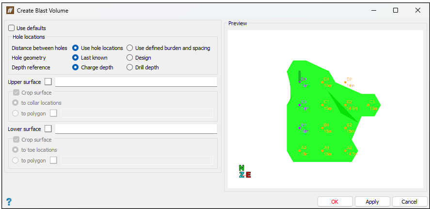
The Create Blast Volume panel will appear.
-
Configure the volume settings. You can either:
-
Select the Use defaults checkbox. In this case, you do not need to provide any details, as BlastLogic will generate the volume with the default settings.
-
Enter volume constraints. To do this:
-
Define the location of holes using the radio buttons in the Hole locations section.
Expand for more information on how BlastLogic calculates the blast volume from the hole location options.
The blast volume calculations can differ depending on whether you select the Design or Last known radio buttons.
-
Design
BlastLogic calculates the blast volume for each hole as a factor of the hole depth, where the depth is calculated using the charge reference surface. If you do not supply a reference surface, the depth is set to the design charge depth and design charge standoff.In this scenario, BlastLogic first converts all of the supplied values for charge standoff to down-hole lengths and then adds them onto the down-hole design charge depth. If you have attached a reference surface, the hole depth is calculated by finding the intersection of the hole with the reference surface. BlastLogic does this by creating a line representing the hole, that extends into the reference surface. This line is the same angle and bearing as the original hole.
-
Last known
The Last known hole location option does not calculate volume using charge standoff. The hole depth is given only by the last known charge depth.The last known charge depth is the either the bottom depth of a loaded charge, or if this has not yet been supplied, the design charge depth.
-
-
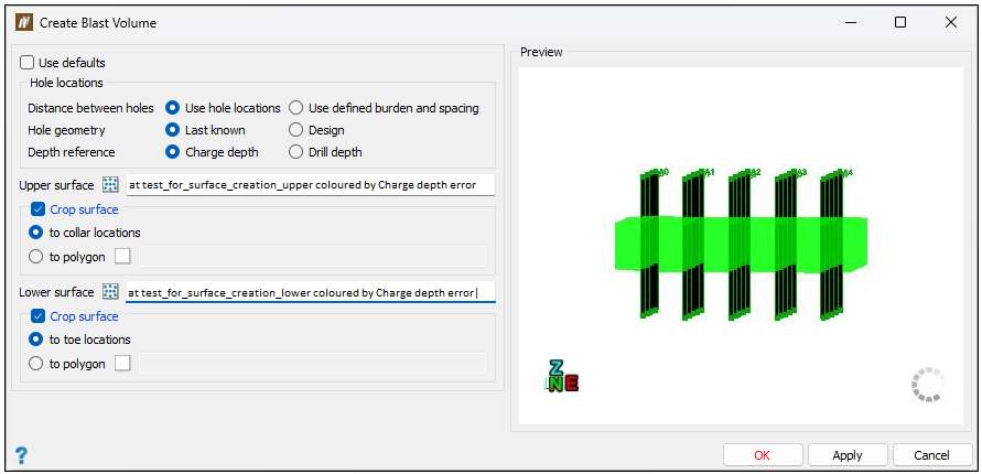
Optionally, enter an upper and lower surface in the Upper surface and Lower surface fields respectively. These surfaces will restrict the volume generation to the surface boundaries. To create a surface, see the Surface from holes or Surface from blasts sections on this page. You can specify these surfaces in the following ways:
-
Drag the desired surface from the
cadcontainer in the project explorer, into the appropriate surface field. -
Enter the location of the desired surface into the appropriate surface field using the format
/cad/<surface name>.
In the surface sections, you can also select the Crop surface checkbox to crop the surfaces to fit around the holes. You can select the following options using the corresponding radio buttons:
-
to collar locations
Crops the surface using the hole collar locations. -
to toe locations
Crops the surface using hole toe locations. -
to polygon
This option requires you to enter the location of a polygon from the
cadcontainer in the project explorer. To create a polygon, see the steps in the Polygon section of the Draw group.Note: If you do not select a cropping option, BlastLogic will crop the surfaces to a best fit around the holes.
-
-
-
-
Click OK or Apply.
BlastLogic will save the blast volume to the
cadcontainer in the project explorer and open it in a new view window.
Adjusting surface geometry
You can check and adjust the geometry of your surface in the following ways:
-
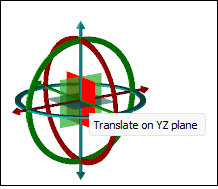
To set the relative angle that the surface would be moved, rotate each plane around each axis:
-
Click on the green circumference of the freehand transform shape and drag the mouse to set the desired angle. This will rotate the surface in the XZ plane around the Y axis. Alternatively, enter the required angle on the keyboard.
-
Click on the red circumference of the freehand transform shape and drag the mouse to set the desired angle. This will rotate the surface in the YZ plane around the X axis. Alternatively, enter the required angle on the keyboard.
-
Click on the blue circumference of the freehand transform shape and drag the mouse to set the desired angle. This will rotate the surface in the XY plane around the Z axis. Alternatively, enter the required angle on the keyboard.
-
-
To translate the surface in each direction:
-
Translate the surface in the X direction by clicking and dragging the red arrow of the freehand transform shape. Alternatively, enter the required shift in the field.
-
Translate the surface in the Z direction by clicking and dragging the blue arrow of the freehand transform shape. Alternatively, enter the required shift in the field.
-
Translate the surface in the Y direction by clicking and dragging the green arrow of the freehand transform shape. Alternatively, enter the required shift in the field.
-
Translate the surface on the YZ plane by dragging the red square at the centre of the freehand transform shape.
-
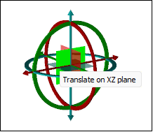
Translate the surface on the XZ plane by dragging the green square at the centre of the freehand transform shape.
-
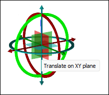
Translate the surface on the XY plane by dragging the blue square at the centre of the freehand transform shape.
-
