

Road Networks in Evolution
Road networks allow Evolution to calculate the time it takes to transport material from one point to another. A road network consists of a number of edges and points that have their own attributes. For example, rolling resistance and speed limit are applied on edges, whereas the ending velocities are applied on points.
Significant points on the road network can be flagged and identified as waypoints. For more information on waypoints, see Waypoints in Evolution.
When you link your waypoints, Evolution will set or interpolate paths between them. Analysing how Evolution classifies each component of a road network will help you understand the way it calculates the best route. See the next sections of this topic for detailed information.
Note: This topic provides general information on road networks in Evolution. We recommend reviewing this content before configuring and analysing road networks in each module. For module‑specific details, see Road Network in Origin Blocks, Road Network in Origin Solids, and Road Network in Epoch.
Road network components
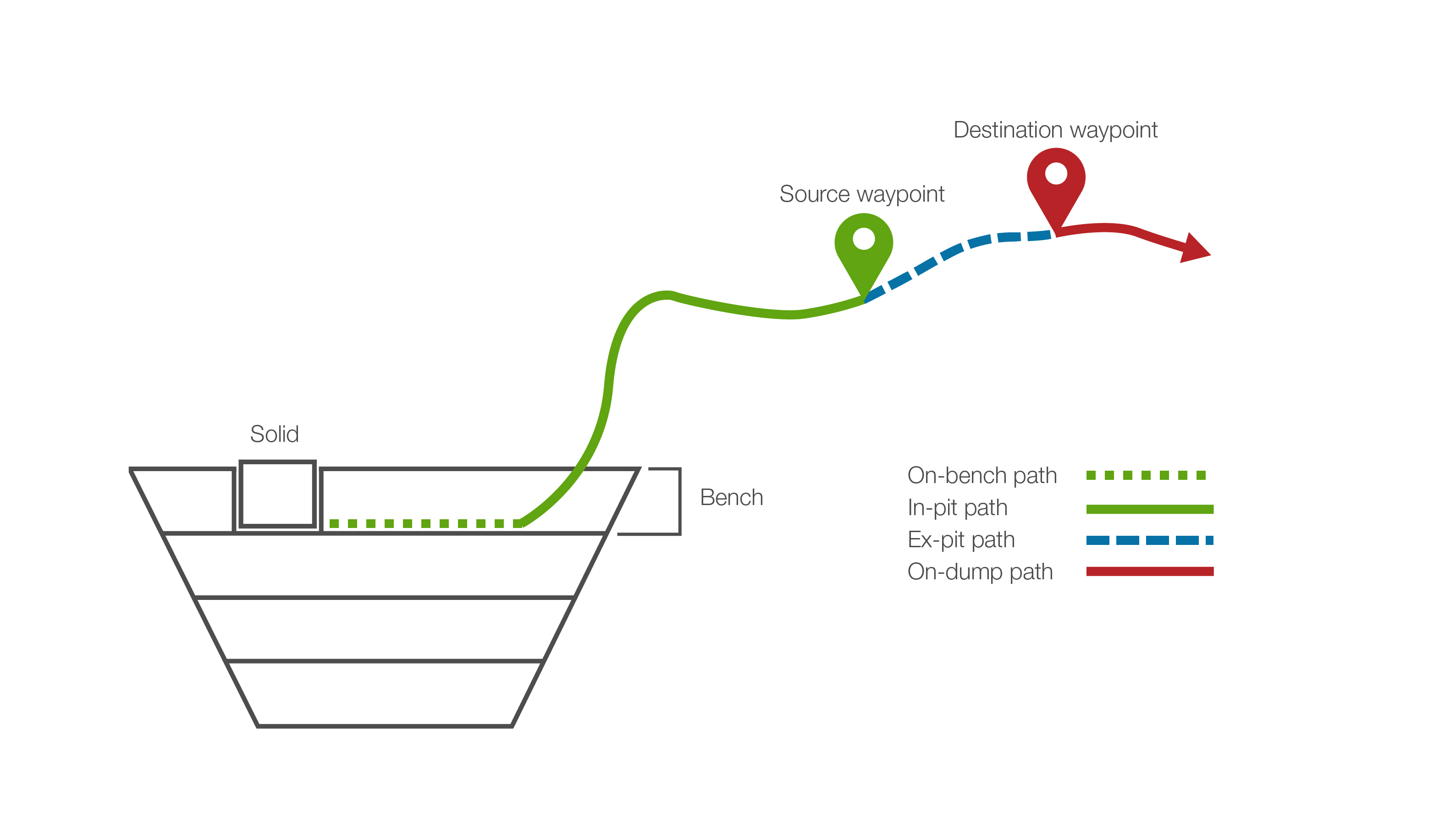
Every road network must include the following components:
-
A solid (or a block in Origin Blocks setups): The source of the mined material.
-
A source waypoint: The exit point onto the road network from the mining pit or stockpile.
-
A destination waypoint: The exit point from the road network to a destination such as a mill, stockpile, or a waste dump.
-
An on-bench path: The pathway from a solid or a block through a ramp point in a bench to the road network.
-
An in-pit path: The path taken from the source solid or block, along the bench to the road network, and along the road network until it reaches a source waypoint.
-
An ex-pit path: The path taken along the road network between a source waypoint and a destination waypoint.
Pathways that end in a waste dump will also contain an on-dump path, a pathway between a destination waypoint, and the site of transfer.
Calculating the best route
When you ask Evolution to transfer the material from a solid to a particular destination, it first calculates all the legal pathways to that destination, by first labelling each edge as in-pit or ex-pit from the perspective of each source waypoint.
Example:
The image below shows the way of calculating the potential in-pit and ex-pit edges from Source A, which is the reference point.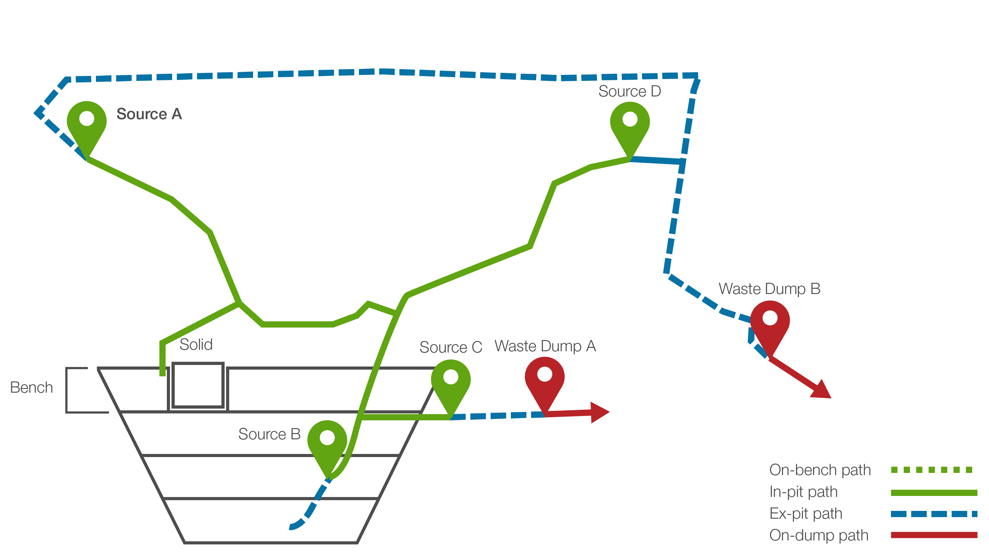
After labelling each edge, Evolution finds the closest ramp point at the same height of the solid (called on-bench path) and then calculates the shortest in-pit path to Source A.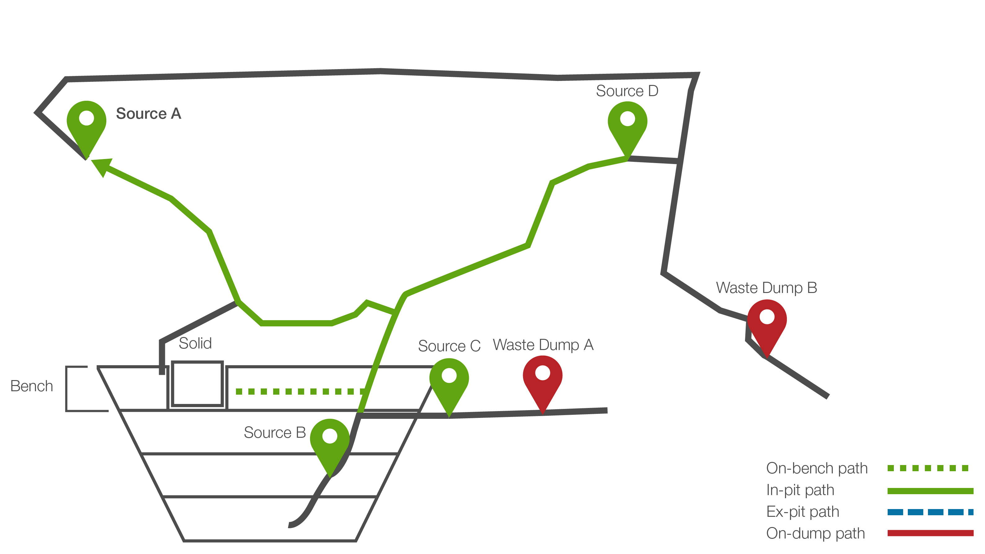
Once Evolution calculates the shortest in-pit path, it can then find a corresponding ex-pit path and calculate the shortest path.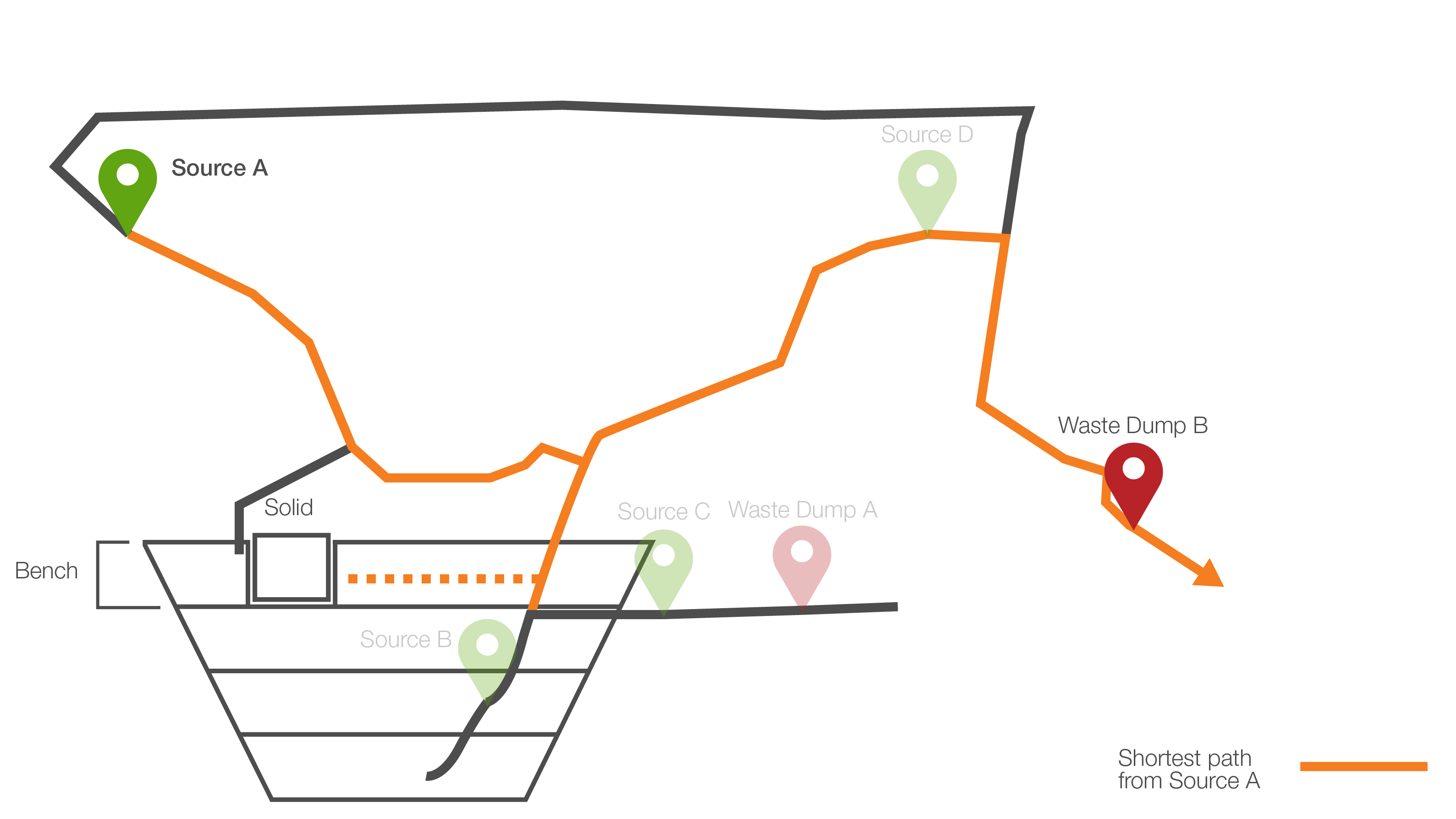
Next, Evolution repeats this process for each source point and then chooses the best path. The best path is the one that has the lowest cost and the least amount of interpolation.
Worked example #1: Internal sources and filters
In the course of calculating the best route, as referenced in the example above, Evolution will identify that the shortest legal paths between the source and mill destination points are between Source B and Waste Dump A, and also between Source C and Waste Dump A, marked in the image below. However, the path from Source B to Waste Dump A would require the digger to drill downwards, which is not a sought-after solution, as it consumes more fuel than driving horizontally.
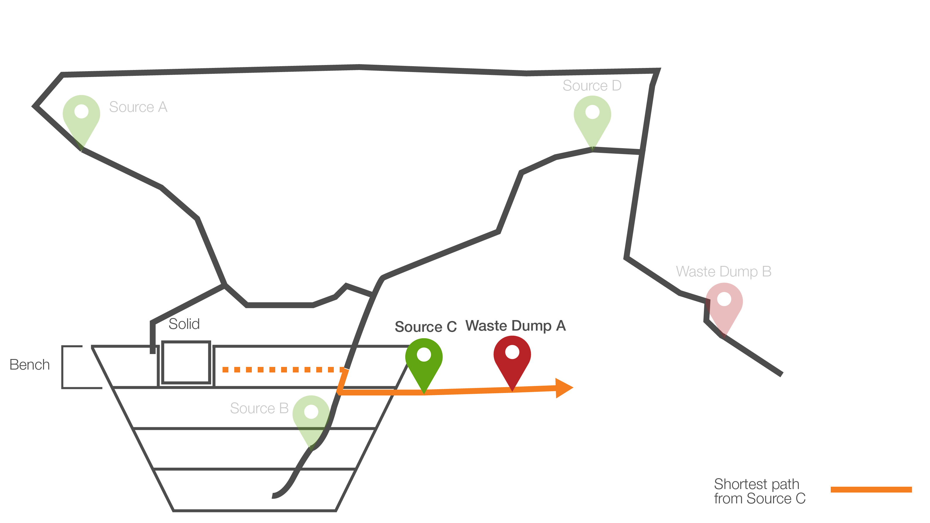
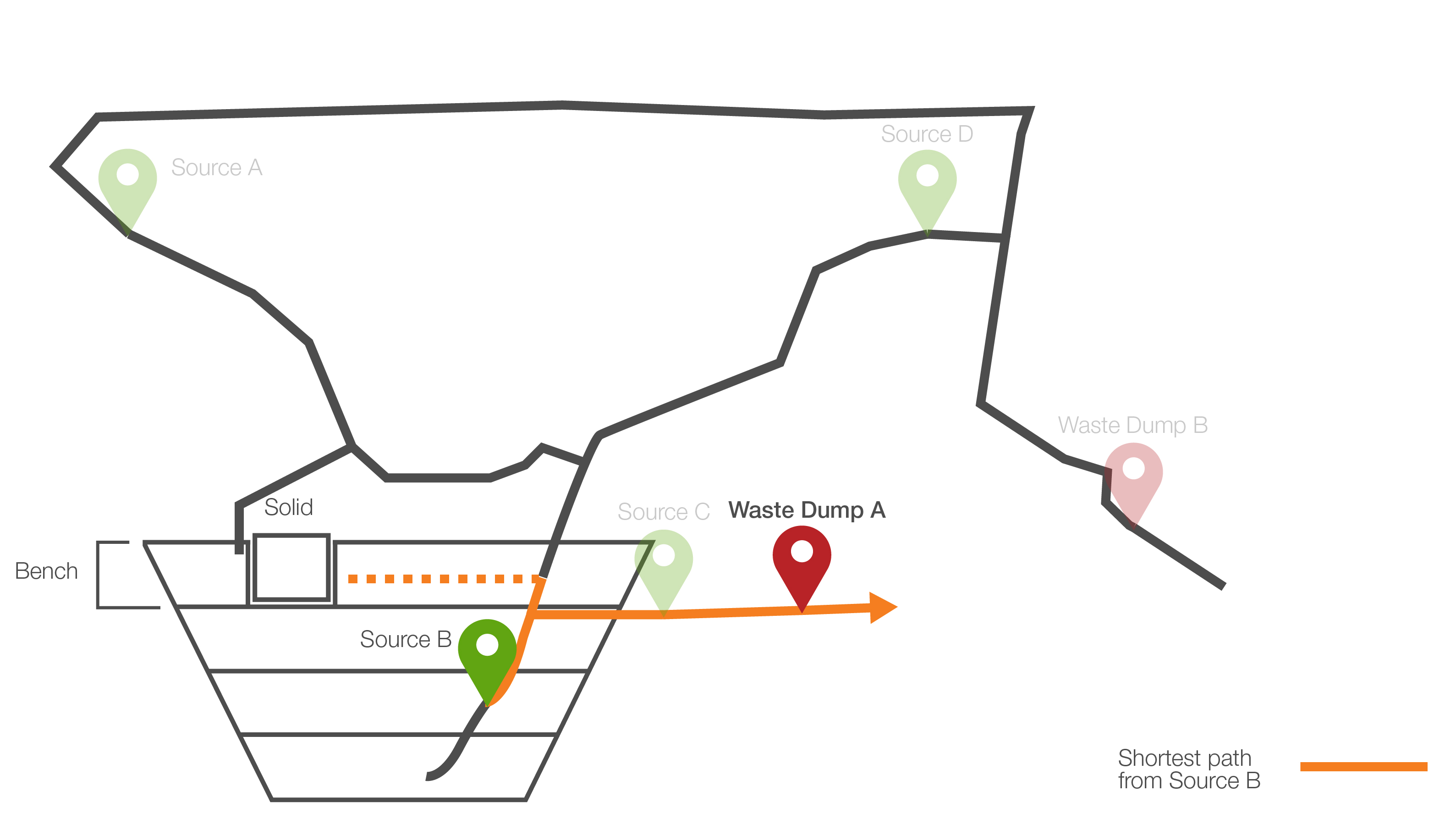
To stop such paths from being chosen, Evolution introduces the use of internal source points and filters.
By flagging a source waypoint as internal, Evolution changes how it classifies potential paths as in-pit, which can result in achieving a more realistic and optimised path. Internal sources can be especially useful when you set the waypoint filters that force certain solids or blocks to be sent through a particular waypoint.
Example:
In the image below, Source B has been marked as an internal source waypoint. As a result, the edges that are directly connected to the reference source waypoint and not directly connected to any other waypoint are considered in-pit.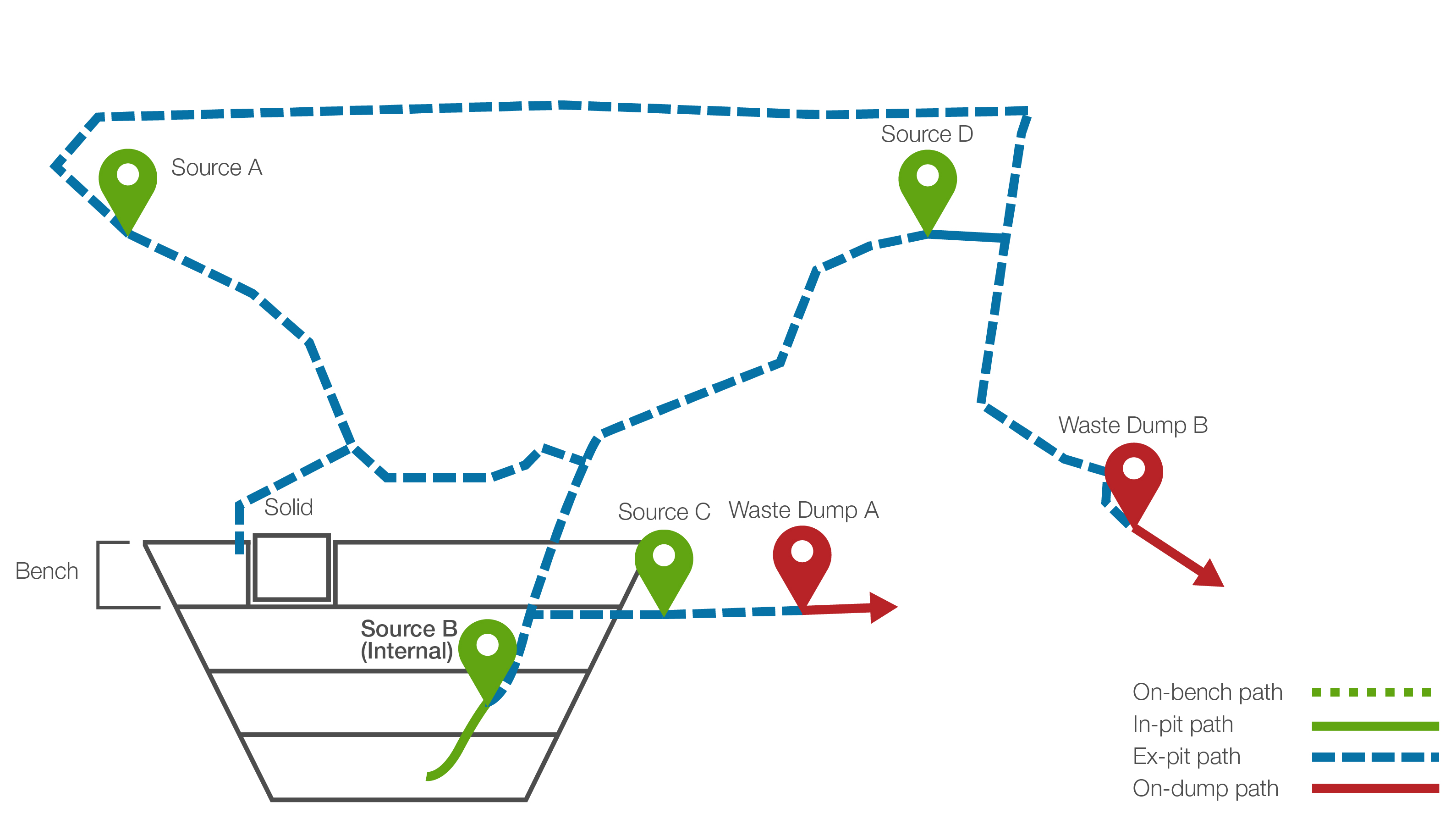
Previously, we defined a pathway as one with a source point, a destination point, an in-pit, and an ex-pit path. As there are no potential in-pit paths connected to Source B at the same height as the solid, the only way for Evolution to create a valid path from Source B to the mill is to create an interpolated pathway between the solid and Source B, as shown in the image below. While this pathway is shorter than those calculated previously, it is ranked lower in preference because it contains an interpolated path.
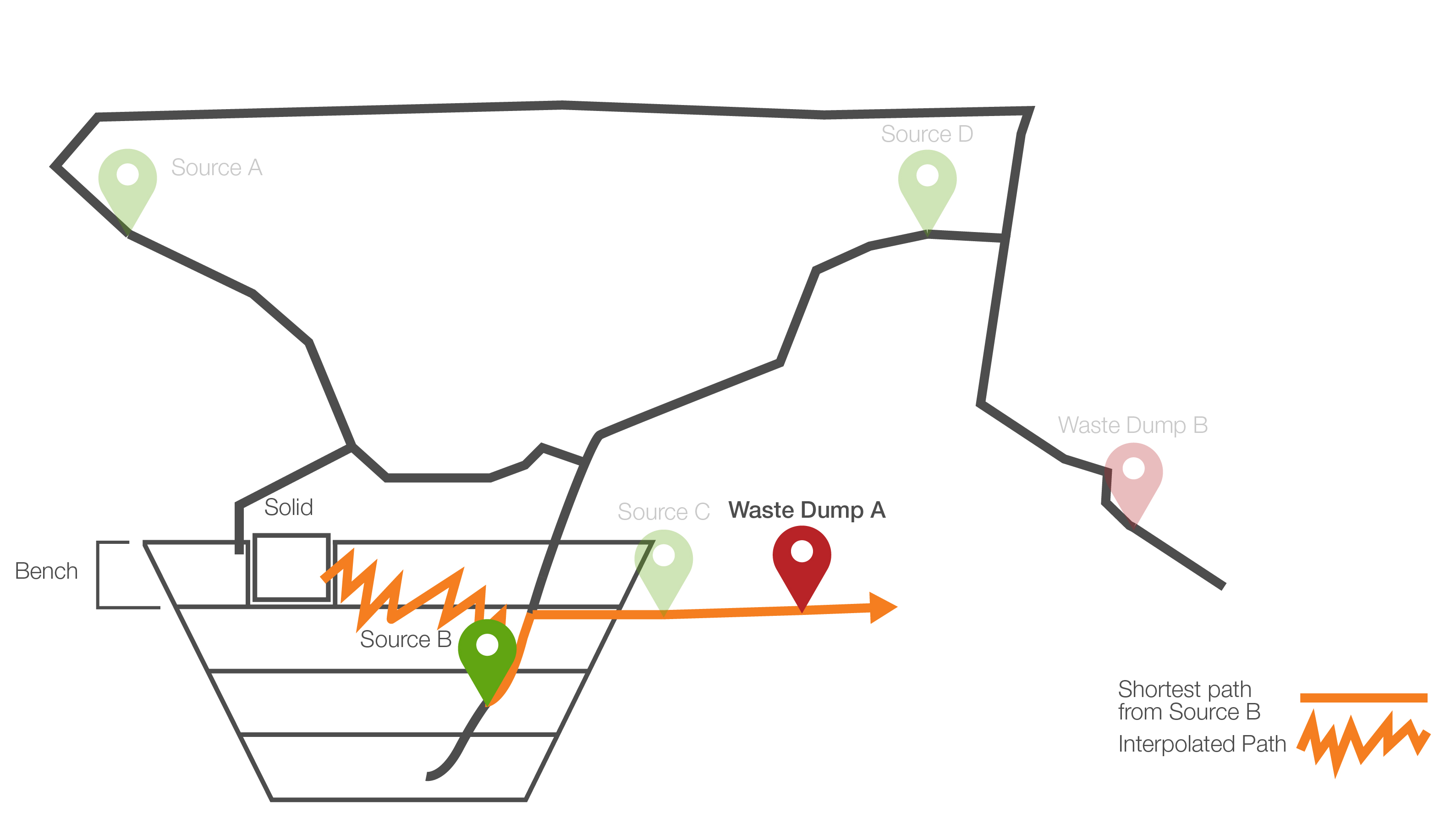
As shown above, the shortest path is still between Source C and Waste Dump A. Apart from flagging source waypoints as internal, you can also apply filters to source points. In the diagram below, the filter solid.bench < 4 is used to prevent downward drilling behaviour. In other words, only material in solids with a bench less than 4 can use this source point to get to a destination. Therefore, calculations from Source C as a reference point will be excluded for the particular solid in question.
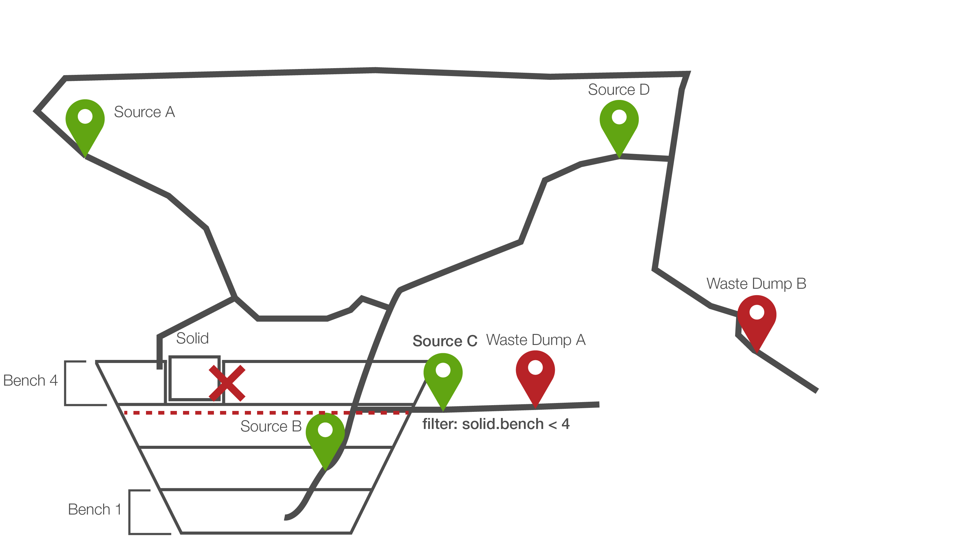
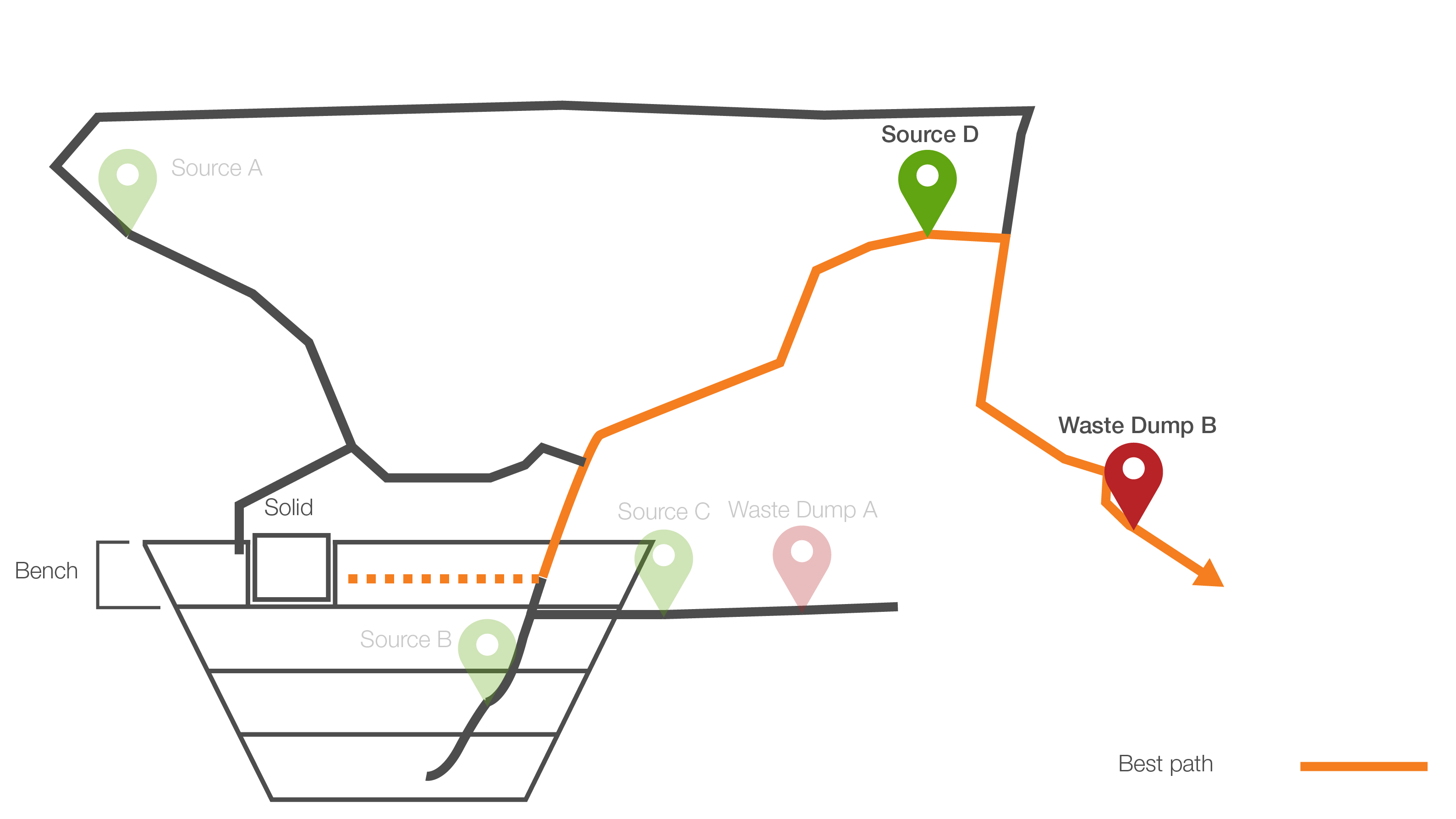
Therefore, the shortest path after applying the filter solid.bench < 4 will now be between Source D and Waste Dump B.
Worked example #2: Exclusive sources
Evolution also allows you to flag source waypoints as exclusive. Making sources exclusive is another way of preventing unrealistic behaviour.
Example:
In the diagram below, the aim is to mine a solid from Bench 4. To avoid downward drilling, which requires more fuel than driving horizontally, the access to source waypoints B and C must be limited. You can mark Source D as an exclusive source and apply the filter solid.bench = 4 to it. This means that solids that belong to Bench 4 will have to go through source waypoint D.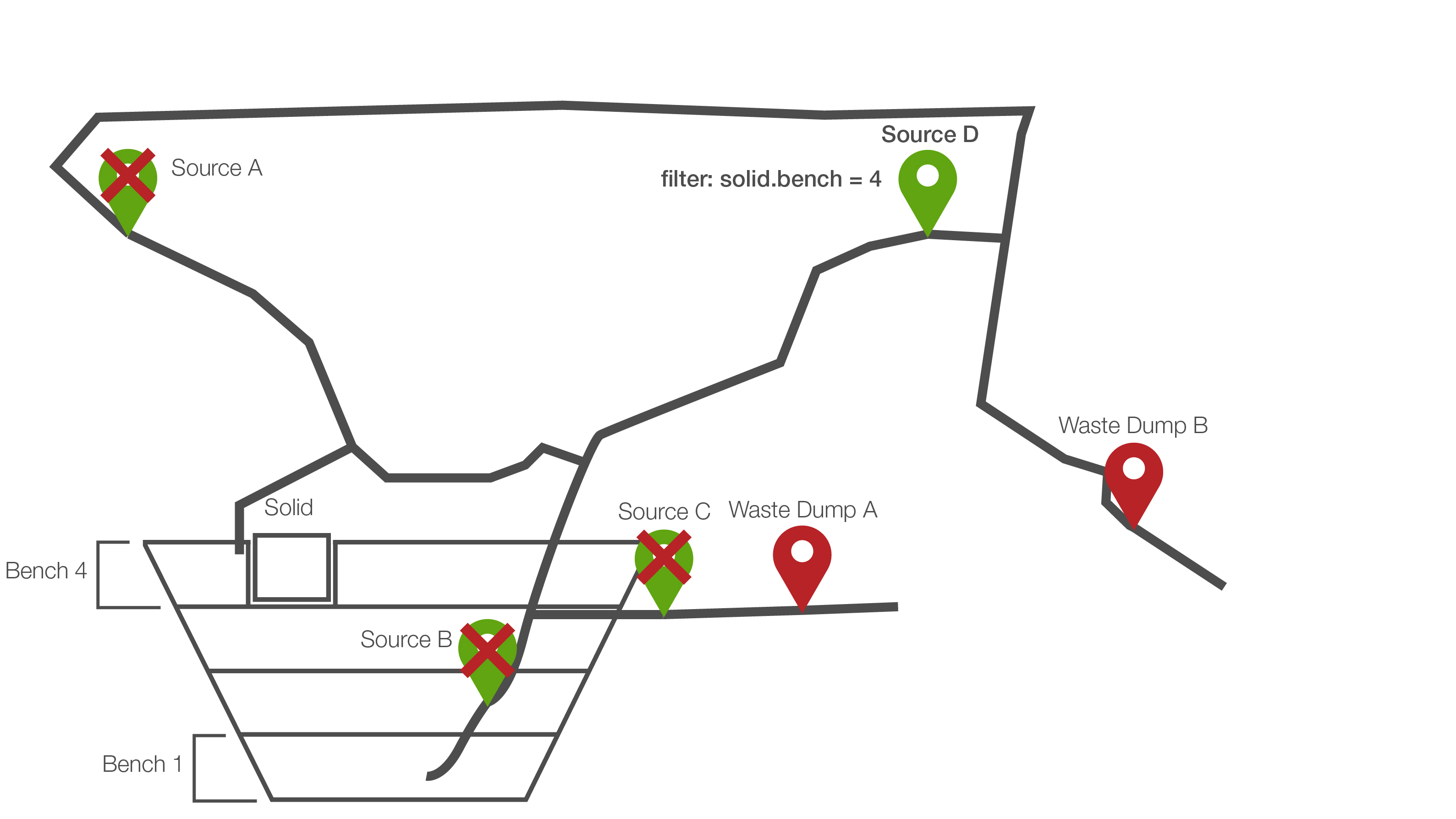
See also: Road network in Origin Blocks, Road Network in Origin Solids, and Road Network in Epoch
Importing and modifying road networks
You can import a road network from a Vulcan design database file (.dgd.isis) or a comma-separated values (.csv) file. You can also link a road network so that it can be shared live with Vulcan. This allows faster editing of the road network based on the mining sequences being produced.
Importing a road network
Follow these steps to import a road network to your setup:
-
Click
 Road Network on the Evolution ribbon.
-
Click Browse to open the file path selector and select the file to import. Alternatively, to create a single road network from multiple files, click Multiple files, then click Browse to select the folder containing the files.
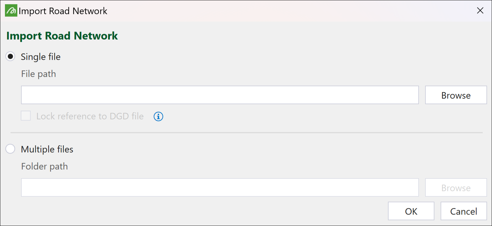
Note: Evolution will import all CSV and Vulcan design database files stored in the selected folder.
Note: When you import a Vulcan design database file, you can lock reference by selecting the Lock reference to DGD file checkbox. This will allow you to live edit in Vulcan.
-
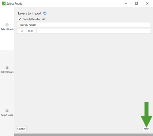
Select the layer to import and click Next.
-
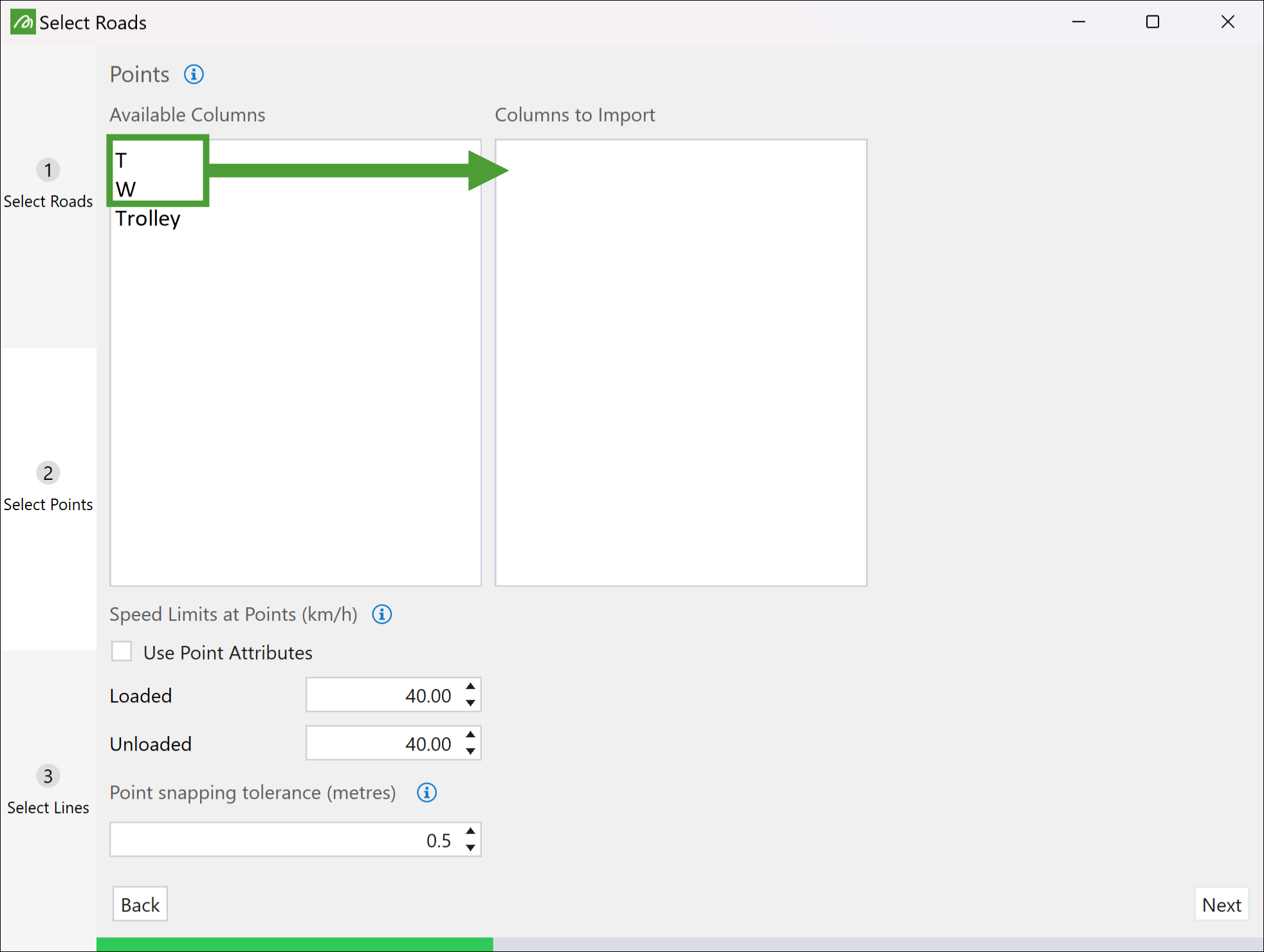
Select the point attributes to import and drag them from the Available Columns to the Columns to Import field.
Note: If you are looking to use a trolley line (conveyor) in Evolution, the Trolley attribute should be selected for edges.
-
Configure the fields under Speed Limits at Points (for Loaded and Unloaded) and Point Snapping Tolerance as required and click Next.
-
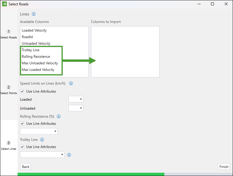
Drag the line-related attributes to be imported from the Available Columns list to the Columns to Import list.
-
Set the Speed Limits on Lines (km/h) section.
-
You can set the values manually by inputting them in the Loaded and Unloaded fields.
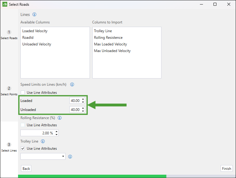
-
To load the preset attributes, select the Use Line Attributes checkbox and select the attributes from the drop-down list. The attributes featured on the list will depend on these imported to the Columns to Import field.
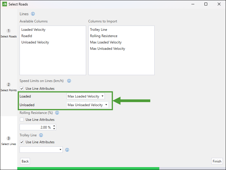
-
-
Set the Rolling Resistance (%) section.
-
You can set the value manually by inputting it in the field. The default value is 2%.
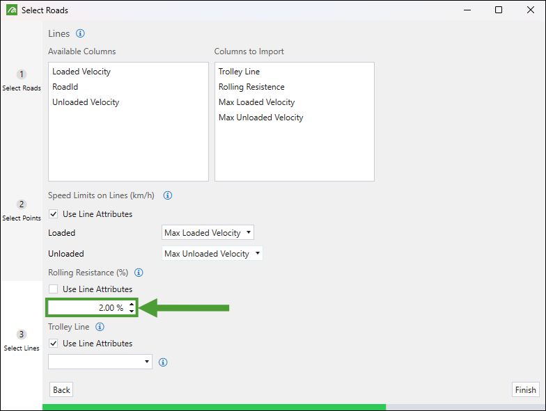
-
To load the preset attribute, select the Use Line Attributes checkbox and select the attribute from the drop-down list. The attributes featured on the list will depend on these imported to the Columns to Import field.
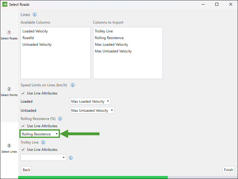
-
-
Set the Trolley Line section:
-
Set the Trolley Line to True if the trucks using this road network will be assisted by a trolley line on all lines.
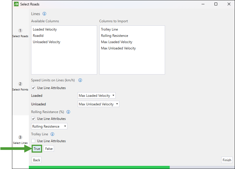
-
If your road network file does not have trolley lines, leave the Use Line Attributes unchecked and select False. This will set every trolley line attribute in the network to False.
-
If only parts of the road network contain trolley lines, you need to specify this with a line attribute. Select the Use Line Attributes checkbox and then choose the trolley line attribute from the drop-down menu.
Note: Evolution will check the line attributes you have loaded to the Columns to Import field list, identify any boolean attributes, and provide them in the drop-down for you to select.
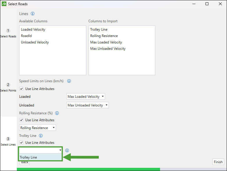
Note: A trolley line attribute can only be of boolean type, thus only boolean type attributes will be listed in the Use Line Attributes drop-down.
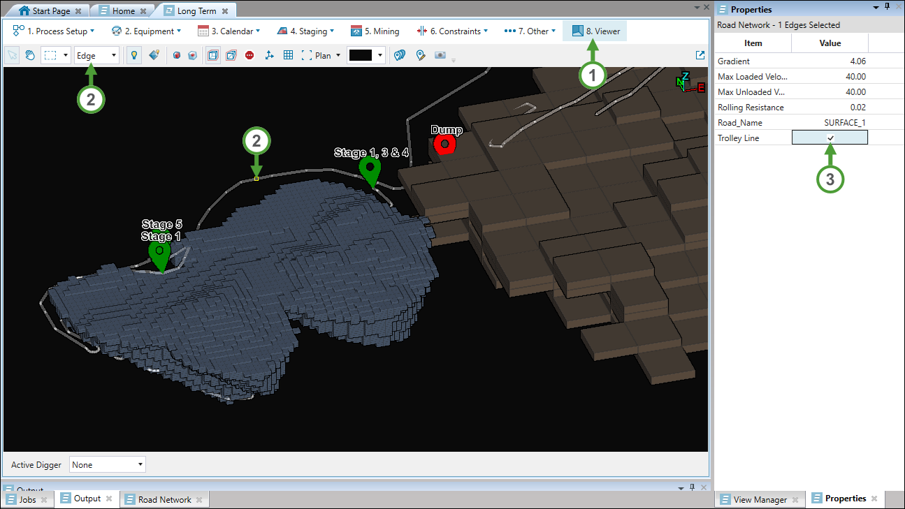
NoteYou can also designate trolley lines manually by following these steps:
-
Load a road network to your viewer.
-
Set the Edge selection type and select the line to which you want to assign a trolley line.
-
Go to the Properties tab on the right side of your screen and select the Trolley Line checkbox.
-
-
-
Click Finish. The road network will be loaded in the viewer.
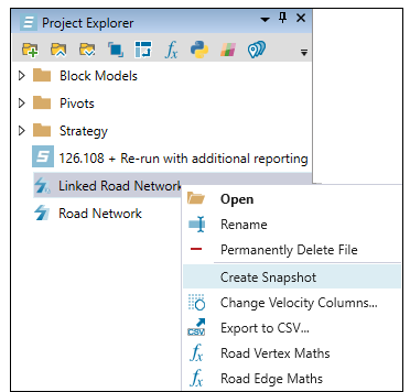
Once the road network is added to a setup, live sharing will no longer be occurring. To keep the live sharing functionality, create a snapshot of the road network by right-clicking on it in the project explorer and selecting Create Snapshot.
Importing a linked road network
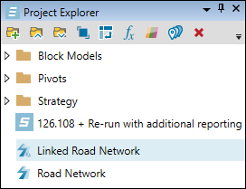
If you have activated the live editing option by selecting the Lock reference to DGD file checkbox while importing a road network (see Importing a road network for more information), the new road network name in the project explorer will be automatically prefixed with the term Linked. This means that any changes made in Vulcan to layers in the file will be reflected in the Evolution viewer.
Modifying road networks
After importing a road network to your setup, you can modify it using the Road Edge Maths script. To enter the script edition tab, right-click on the road network in your project explorer and select  Road Edge Maths.
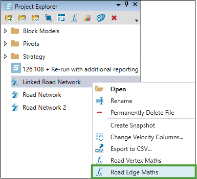
Evolution will create a Maths Scripts folder for the given road network in the project explorer (if you have not modified maths scripts for that road network before) and create a Road Edge Maths file within that folder. Double-click the Road Edge Maths file to enter the script editor.
In the script editor, enter the appropriate formula and click  Run Formula to apply it.

Important: Since the Trolley Line attribute is a boolean value, it needs to be set to 1 (true) or 0 (false).
A dialog window informing you about overwriting the existing attributes by the newly applied formula will appear. Click Yes if you wish to proceed.

Viewing a road network
If you import a road network, the viewing options will become available in the viewer tab. Use the following features to improve the visibility of the required parts of the road network:
Adding quick colours
A quick colour is a collection of colours you can use to visualise the values of a selected attribute in a road network model.
To apply a quick colour to a road network, complete the following steps:
-
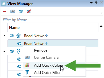
Right-click the road network model in the View Manager to open the context menu and select
 Add Quick Colour.
-
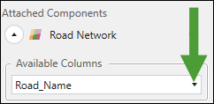
Select the required road network attribute from the Available Columns drop-down.
-
Specify the comparison method by selecting one of the following radio buttons:
-
Ranged. Set the range of values to generate the colours.
Note: This option is not available for every road network attribute.
-
Equality. Assign a separate colour to each distinct attribute value.
-
-
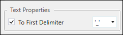
Select the To First Delimiter checkbox to extract only the portion of the text before the first delimiter character, then specify the character by selecting it from the drop-down.
-
Select the colour scheme from the drop-down.
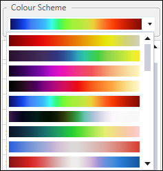
Evolution will apply the colours to each value corresponding to the selected road network attribute.
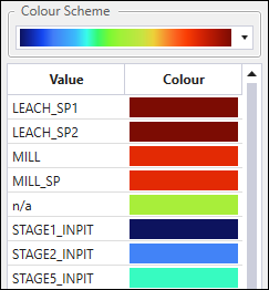
Tip: To change a colour applied to an attribute, double-click on that colour and select the colour from the available options.
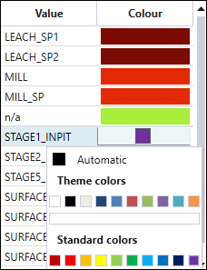
The selected colours will be reflected in the viewer.
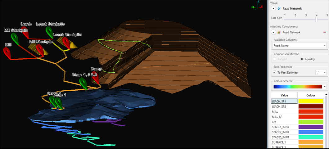
Tip: Use the dynamic filters to improve the visibility of the road network components in the viewer. Depending on the module in which you are configuring your setup, refer to Dynamic Filter in Origin Blocks, Dynamic Filter in Origin Solids, or Dynamic Filter in Epoch for details.
-
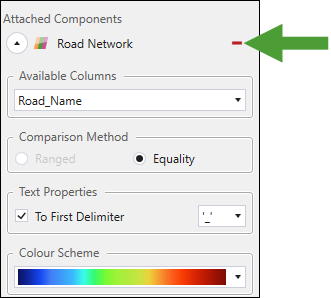
To remove the applied quick colours from your view, click
 (Detach Component From Visual).
-
Adding quick filters
Quick filters allow you to narrow the road network elements shown in the viewer.
To apply quick filters to a road network, follow these steps:
-
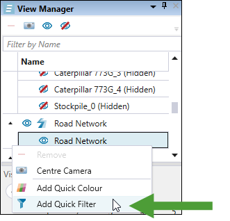
Right-click the road network model in the View Manager to open the context menu and select
 Add Quick Filter.
-
Filter the road network by the following properties:
-
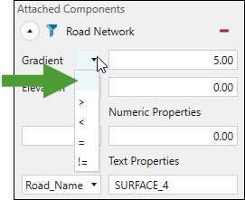
Gradient. Using the drop-down, select the required mathematical relation from the following and enter the required value:
-
> (Greater than)
-
< (Less than)
-
= (Equal to)
-
!= (Not equal to)
-
-
Elevation. Using the drop-down, select the required mathematical relation from the following and enter the required value:
-
> (Greater than)
-
< (Less than)
-
= (Equal to)
-
!= (Not equal to)
-
-
Numeric Properties. Using the drop-down, select the truck movement parameter (Max Loaded Velocity, Max Unloaded Velocity, or Rolling Resistance) and enter the required value. For more information on setting the truck parameters, see Max Speed in Origin Blocks, Max Speed in Origin Solids, or Max Speed in Epoch, depending on the module in which you are configuring your setup.
-
Text Properties. Using the drop-down, select the text property assigned in your road network and enter the required name.
Evolution will directly apply the set filters in the viewer.
-
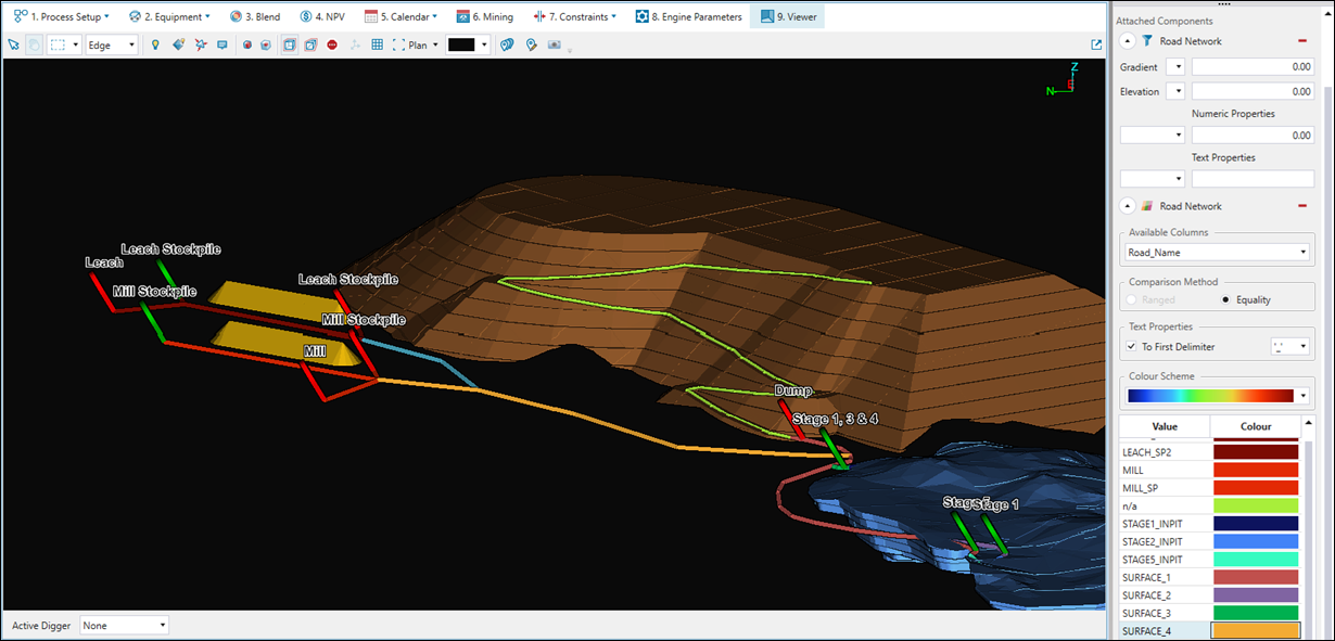
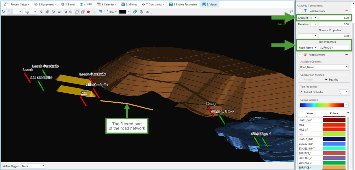
The table below compares the road network visibility before and after applying quick filters in the viewer. The road network was filtered by section name (SURFACE_4) and by road gradient values greater than 5.
| Before applying the quick filters | After applying the quick filters |
|---|---|
|
|
-
To remove the applied quick filters from your view, click
(Detach Component From Visual).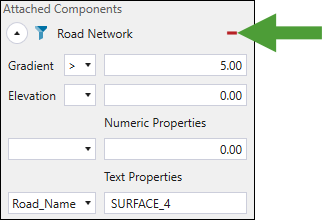
-
To temporarily disable the applied filter, select the blank space from the corresponding drop-down menu.
Depending on the module in which you are configuring your setup, see also the following topics:
Road mathematics
Road edge maths and road vertex maths scripts allow you to modify attribute values on the edges or vertices of a road network. These scripts work in the same way as other maths scripts in Evolution, but use edge. or vertex. to reference road network attributes.
Note: The syntax is identical to maths scripts used elsewhere in Evolution—only the prefix changes.
See also: Maths Scripting
To create and execute a road maths script, follow these steps:
-
Right-click on a road network in the project explorer and select
Road Vertex Maths or Road Edge Maths. This will create an empty script.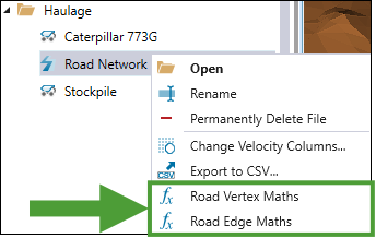
In the project explorer, under the road network model, Evolution will create a script object corresponding to the context menu option that you selected.
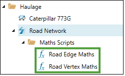
Double-click the required script object to open the script window in the viewer.
-
Write your formula in the script.
Note: To reference an attribute on the road network, type edge. or vertex. followed by a full stop. A list of available columns will appear for you to select from.
Exampleloadedvelocity = if(edge."Max Loaded Velocity" > 40, "high", "low")
loadedvelocity = if(vertex."Loaded Velocity" > 40, "high", "low")
-
Click
Run Script to execute the script and update the chosen attributes on the road network.Tip: Apply a quick colour to the road network in the view manager to visualise the updated attribute values. See Adding quick colours for details.
