Calculate Drill Traces
This section allows users to run the drillhole creation parameters to preview the holes that will be created. Once calculated, options to edit one or more holes become available so as to refine the drill program.
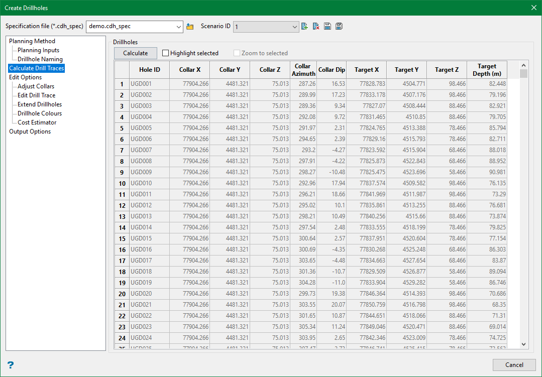
Calculate uses the Planning Method, Planning Inputs and the Drillhole Naming parameters to populate the relevant values in the grid and display the drillholes on the Vulcan screen. The drill traces that are calculated are simple linear drillholes comprised of a collar and target point, with survey intervals spaced according to the Survey Interval parameter.
The default colours applied to the calculated drillholes are:
- Collar and hole layout — The drillholes are coloured according to the colour of the collar point objects selected. However, if the Collar colour is invalid (i.e. the colour value has been removed/deleted from the Planning Inputs grid, or if the Collars have been defined using the digitise option), the colour in the Drillhole Colours panel will be used. The default colour in this panel is colour index 2 from the colour palette.
- Collar and target — The drillholes are coloured according to the colour of the target point objects selected. However, if the target colour is invalid, then the Collar colour is used given that it is valid, otherwise the colour in the Drillhole Colours panel will be used.
- Target and hole layout — The drillholes are coloured according to the colour of the target point objects selected. However, if the Collar colour is invalid, the colour in the Drillhole Colours panel will be used.
- Daughter hole — The drillholes are coloured according to the colour in the Drillhole Colours panel.
Highlight selected
Select this option and click on the row number in the grid to highlight the drillholes. The selected drillholes will be highlighted on the screen.
Zoom to selected
Select this option to zoom to the selected drillholes on the screen.
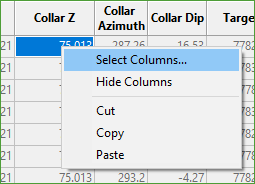
You can make changes to the display of the columns in the grid by right-clicking on the column header row and then selecting Select Columns.
This displays the following panel. Choose the columns that you want to display in the grid.
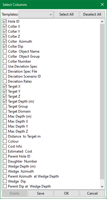
All the column names and their descriptions are given in the table below.
| Column Name | Description |
| Hole ID |
The name of the drillhole, as determined by the parameters defined in the Drillhole Naming panel. |
| Collar X |
The X coordinate of the collar position. |
| Collar Y | The Y coordinate of the collar position. |
| Collar Z | The Z coordinate of the collar position. |
| Collar Azimuth | The Azimuth of the drillhole at the collar position. |
| Collar Dip | The Dip of the drillhole at the collar position. |
| Collar Object Name | The Name of the object that was used to define the collar position. |
| Collar Object Group | The Group of the object that was used to define the collar position. |
| Collar Number | Each separate collar point selected is assigned a number index as a way of grouping the drillholes by each collar location. |
| Use Deviation Spec | A checkbox field that stores whether or not a deviation specification file has been used to apply deviation to the drillhole. |
| Deviation Spec File | The deviation specification file that has been applied to the drillhole. |
| Deviation Scenario ID | The Scenario ID from the chosen deviation specification file that has been applied to the drillhole. |
| Deviation Rates | The deviation rates that have been applied to the drillhole. |
| Target X | The X coordinate of the target position. |
| Target Y | The Y coordinate of the target position. |
| Target Z | The Z coordinate of the target position. |
| Target Depth | The downhole depth of the target. |
| Target Group | The Group of the object that was used to define the target position. |
| Target Domain | The Domain of the object that was used to define the target position. |
| Max Depth | The maximum (end of hole) downhole depth of the drillhole. |
| Max Depth X | The X coordinate of the maximum downhole depth position. |
| Max Depth Y | The Y coordinate of the maximum downhole depth position. |
| Max Depth Z | The Z coordinate of the maximum downhole depth position. |
| Distance to Target | The shortest distance calculated from the drill trace to the target position, when applying deviation to drillholes using the Collar and Target planning method. |
| Colour | The current colour of the drillhole. The assigned colour only applies when saving the drillholes to a design database layer, not when saving to an isis database or CSV files. |
| Cost Info | The depth thresholds and associated cost rates applied to the drillhole. |
| Estimated Cost | The estimated cost, calculated from the Max Depth and applied Cost Info. |
| Parent Hole ID | The Hole ID of the parent drillhole used to create the daughter holes from, when creating drillholes using the Daughter hole planning method. |
| Wedge Depth | The depth downhole of the parent drillhole where the daughter hole will wedge off from, when creating drillholes using the Daughter hole planning method. |
| Wedge Azimuth | The azimuth of the daughter hole at the Wedge Depth, when creating drillholes using the Daughter hole planning method. |
| Parent Azimuth at Wedge Depth | The azimuth of parent drillhole at the Wedge Depth, used as a reference when creating drillholes using the Daughter hole planning method. |
| Wedge Dip | The dip of the daughter hole at the Wedge Depth, when creating drillholes using the Daughter hole planning method. |
| Parent Dip at Wedge Depth | The dip of parent drillhole at the Wedge Depth, used as a reference when creating drillholes using the Daughter hole planning method. |
Related Topics
- Evaluate Drill Density
- Create Drill Targets
- Create Drillholes
- Edit Drillholes
- Reporting
- Deviation Calculation Manager
- Drill Rig Setup Specification
- Cost Estimation Specification
- Reposition Hole
- Convert Object to Drillhole

