Planning Inputs
The options available in this section depend on the type of planning input selected in the Planning Method section.
There are four types of planning methods:
Collar and hole layout
See Planning Input Type.
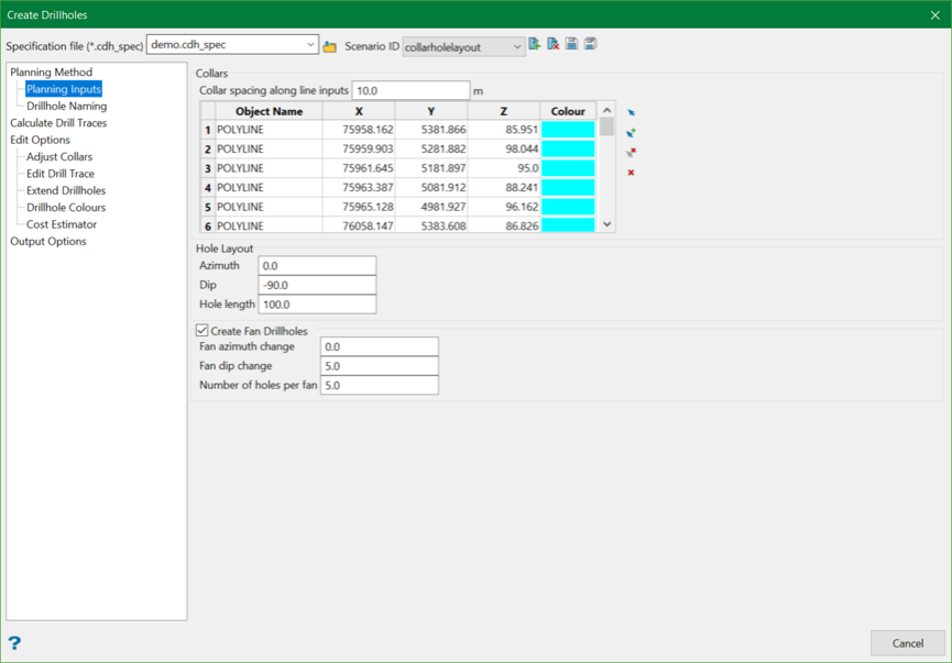
Collars
Select the desired collar points that will be used to create drillholes. Collars can be chosen either by selecting points interactively, by selecting point and polyline objects on the screen using the Select option, or by digitising a new collar point location using the Digitise option from the controls available on the right.
Collar spacing along line inputs
When polyline objects are selected as collar inputs, individual collar points will be calculated along the polyline object(s) at the specified collar spacing. These calculated points are used to populate the grid.
Hole Layout
These parameters (Dip, Azimuth, and Hole length) define the orientation at the collar and length of the drillholes that will be created from the selected collars.
Create fan drillholes
These parameters allow the creation of a fan of drillholes that fan out from the drillhole designed with the Collar and Hole Layout parameters. The following parameters are required for fan drillholes:
- Fan azimuth change — The adjustment to the collar azimuth of each fan drillhole radiating out from the initial drillhole design.
- Fan dip change — The adjustment to the collar dip of each fan drillhole radiating out from the initial drillhole design.
- Number of holes per fan — The extra number of drillholes that will be created as part of each fan. This number does not include the original drillhole the fan is based on.
Example
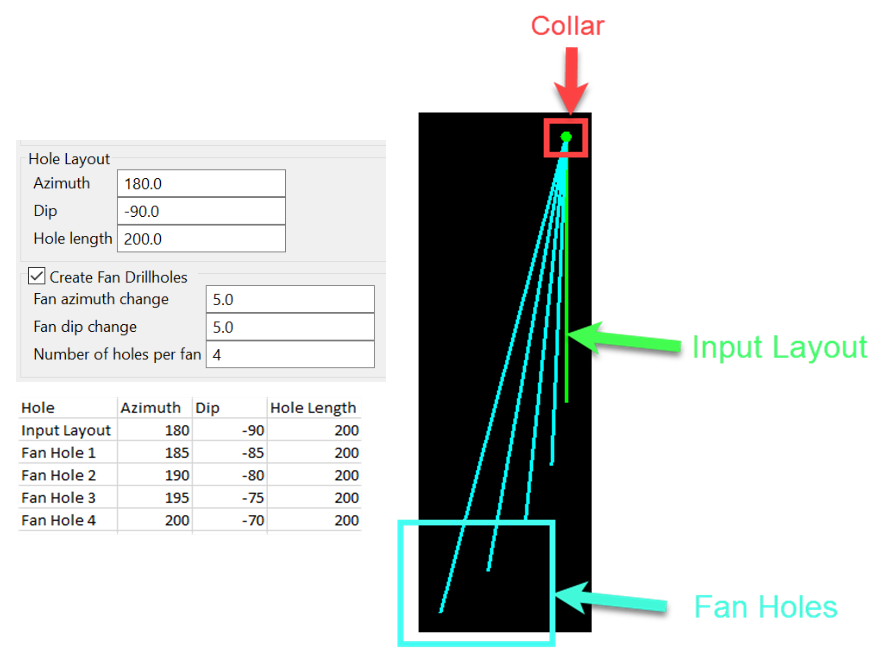
Figure 1 : The position of the collar, hole layout, and fan holes
Collar and target
See Planning Input Type.
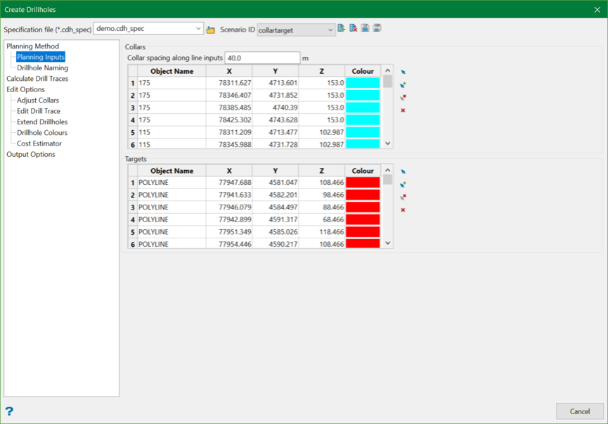
Collars
Select the desired collar points that will be used to create drillholes. Collars can be chosen either by selecting points interactively, by selecting point and polyline objects on the screen using the Select option, or by digitising a new collar point location using the Digitise option from the controls available on the right.
Collar spacing along line inputs
When polyline objects are selected as collar inputs, individual collar points will be calculated along the polyline object(s) at the specified collar spacing. These calculated points are used to populate the grid.
Targets
Select the desired target points that will be used to create drillholes. Targets can be chosen either by selecting points interactively, by selecting point and polyline objects on the screen using the Select option, or by digitising a new collar point location using the Digitise option from the controls available on the right.
Target and hole layout
See Planning Input Type.
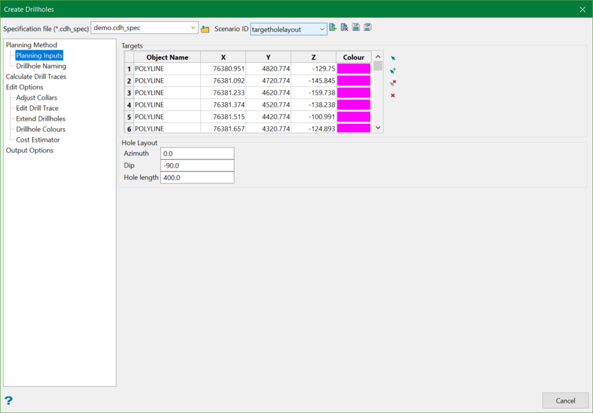
Targets
Select the desired target points that will be used to create drillholes. Targets can be chosen either by selecting points interactively, by selecting point and polyline objects on the screen using the Select option, or by digitising a new collar point location using the Digitise option from the controls available on the right.
Hole Layout
These parameters (Dip, Azimuth, and Hole length) define the orientation at the collar and length of the drillholes that will be created from the selected collars.
Note: It is important to note that the azimuth and dip value relates to the desired value at the collar.
Daughter hole
See Planning Input Type.
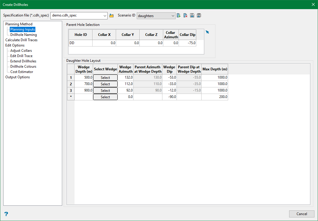
Parent Hole Selection
Select the desired parent drillhole that will be used to create wedge drillholes from. The parent drillhole can be interactively selected on the screen using the Select option from the control available on the right.
Daughter Hole Layout
This defines the parameters that are used to create the daughter drillhole(s).
Wedge Depth
The downhole depth of the parent drillhole from which to wedge off the daughter hole. This depth value can be entered manually or selected interactively from the screen using the Select button in the Select Wedge column in the grid.
Wedge Azimuth
This is the azimuth value to be applied at the wedge depth of the daughter hole.
Parent Azimuth at Wedge Depth
This is the calculated azimuth of the parent drillhole at the defined wedge depth, provided as a reference when determining the Wedge Azimuth.
Wedge Dip
This is the dip value to be applied at the wedge depth of the daughter hole.
Parent Dip at Wedge Depth
This is the calculated dip of the parent drillhole at the defined wedge depth, provided as a reference when determining the Wedge Dip.
Max Depth
This is the maximum depth of the daughter drillhole, measured from the collar of the parent drillhole, as demonstrated in the image below.
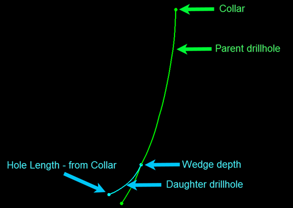
Figure 2 : Max depth of Daughter Hole with respect to Wedge Depth
Related Topics
- Evaluate Drill Density
- Create Drill Targets
- Create Drillholes
- Edit Drillholes
- Reporting
- Deviation Calculation Manager
- Drill Rig Setup Specification
- Cost Estimation Specification
- Reposition Hole
- Convert Object to Drillhole

