Deviation Calculation Manager
Use this tool to calculate the expected deviation of new drillholes, based on the orientation and depth of holes in an existing drillhole database. The resulting deviation specifications are used in the Create Drillholes or Edit Drillholes tools to incorporate expected deviation into the drill plan.
Instructions
On the Geology menu, point to Drillhole Planning, then click Deviation Calculation Manager to display the following panel.
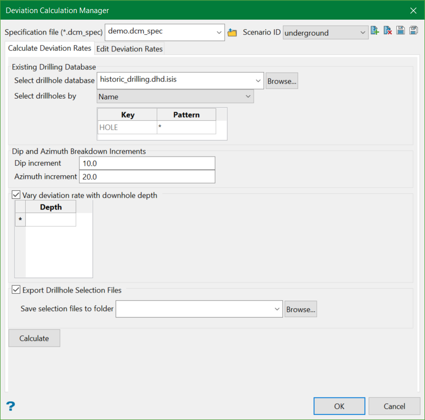
The panel is divided into two sections:
Specification file
Use the drop-down list to select the specification file if it is in the current working directory, or browse for it in another location by clicking the Browse button. A new file may also be created by typing the name of the new file in the textbox.
Scenario ID
Use the drop-down list to select the ID file, or create a new one by clicking the New icon.
-
 New
New -
 Delete
 -
 Save
Save -
 Save as
Note: The specification file (*.dcm_spec) is mandatory to run this tool and is used to store the calculated deviation rates.
Calculate Deviation Rates
Existing Drilling Database
Select drillhole database
Select the desired isis drillhole database to be used in the calculation of the deviation rates. You can select the existing database from the drop-down list or browse from another directory.
Select drillholes by
Drillholes can be selected in three ways:
- Name —Allows applying a filter based on the input pattern. For example, if the prefix
UGDis used for all underground drillholes in the database and only these drillholes were to be used in the calculation, thenUGD*could be input as the Pattern. The default*is used as a wildcard to select all drillholes in the database. - Selection file —Allows using a drillhole selection file (
.sel) to restrict using the holes whoseHoleIDis contained in the selection file.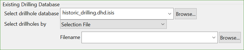
- Exclusion file —Allows using a drillhole selection file (
.sel) to restrict using the holes whoseHoleIDis not contained in the selection file.
Dip and Azimuth Breakdown Increments
The average deviations are calculated for regions of similar orientation, allowing for different deviation based on drilling direction. It is important to calculate the average deviation rates for dip and azimuth values with respect to different azimuth and dip quadrants. This allows for a more localised control over the dip and azimuth deviation rates calculated and used.
Dip increment
In deposits where drilling occurs in multiple orientations, it is important to compare data drilled in similar orientations. For example in Figure 1, the average dip deviation rates of all holes that fall into the purple azimuth quadrant need to be calculated separately from those that fall into the green azimuth quadrant. This is important because, depending on the geology, the azimuth at which the hole is drilled can impact the deviation observed in the dip.
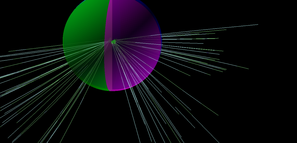
Figure 1 : 3D view showing how some drillholes would align with the azimuth quadrants
The Dip increments (bins) define the increments at which the average dip deviation rates can be calculated. Typical values would be 10° increments for dip, although this may differ depending on the amount of available drilling.
The dip deviation rates are split into quadrants based on 45° increments, totalling 180°. When the dip switches past -90°, it flips the azimuth value by 180°. Example, if a hole of azimuth 90° and dipping at -89.5° were to shift 0.5° past -90°, it becomes -89.5° towards 270°.
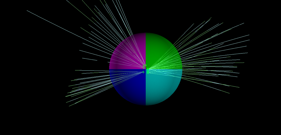
Figure 2 : Plan view showing how some drillholes would align with the azimuth quadrants
Azimuth increment
In deposits where drilling occurs in multiple orientations, it is important to compare data that is drilled in similar orientations. For example in Figure 3, the average azimuth deviation rates of all holes that fall into the dark blue dip quadrant need to be calculated separately from those that fall into the light blue dip quadrant. This is important because, depending on the geology, the dip at which the hole is drilled can impact the deviation observed in the azimuth.
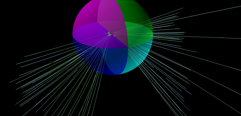
Figure 3 : 3D view showing how some drillholes would align with the dip quadrants
The Azimuth increments (bins) define the increments at which the average azimuth deviation rates can be calculated. Typical values would be 20° increments for azimuth, although this may differ depending on the amount of available drilling.
The azimuth deviation rates are split into quadrants based on 90° increments. This is to account for calculating the deviation rates on 'like-for-like' data, irrespective of the orientation.
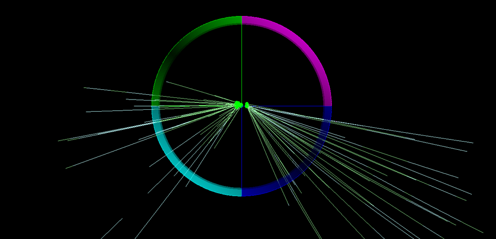
Figure 4 : Cross-section view showing how some drillholes would align with the dip quadrants
Vary deviation rate with downhole depth
The rate of deviation may change downhole based on factors such as the type of geology and drilling conditions. Selecting this option allows deviation calculations to be broken down by downhole depth increments when required. To see this in action, refer Depth Threshold.
Example: A useful scenario where this option can be used is when analysing holes drilled from surface that transition through alluvial material, before transitioning to units with a different deviation rate, such as foliated metasediments.
Depth
The downhole depth increments (bins) at which the average dip and azimuth deviation rates can be calculated.
Export Drillhole Selection Files
Viewing the holes that make up each of the average deviation bins is useful for understanding the data available to make these calculations.
This option allows drillhole selection files to be generated and saved for each dip and azimuth bin, which may be used to restrict the holes that are loaded in Vulcan using Load Drillholes option.
Calculate
Once everything is set, click this button to run the actual calculation process.
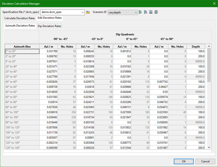
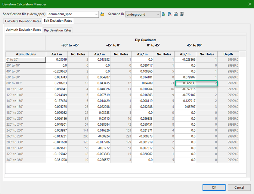
Edit Deviation Rates
The calculated deviations rates are displayed in a table based on the Azimuth and Dip breakdowns.
Azimuth Deviation Rates
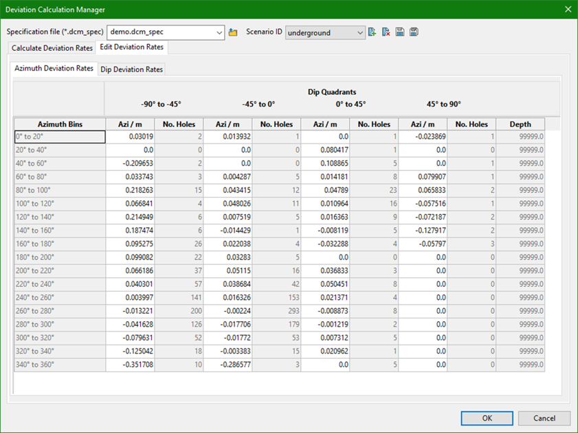
Azimuth Bins
The increments (bins) at which the average azimuth deviation rates were calculated.
Dip Quadrants
The azimuth deviation rate bins have been split based on 45° dip increments (quadrants).
Azi/unit
The calculated average change in azimuth per unit (as defined in the DG1) for each bin.
No. Holes
The number of drillholes that were used to calculate the Azi/unit value.
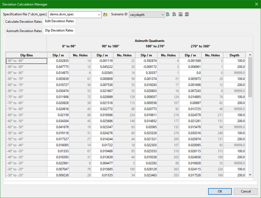
Dip Deviation Rates
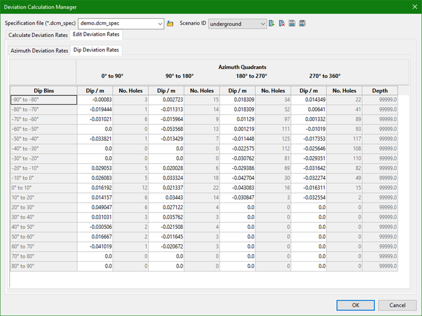
Dip Bins
The increments (bins) at which the average dip deviation rates were calculated.
Azimuth Quadrants
The dip deviation rate bins have been split based on 90° azimuth increments (quadrants).
Dip/unit
The calculated average change in dip per unit (as defined in the DG1) for each bin.
No. Holes
The number of drillholes that were used to calculate the Dip/unit value.
Depth Thresholds
If the Vary deviation rate with downhole depth option is selected in the Calculate Deviation Rates section, then separate rows are created for each threshold.
For example, let's take the following depth thresholds.
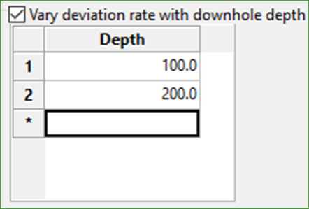
Azimuth Deviation Rates
Dip Deviation Rates
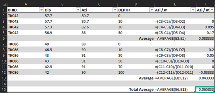
Calculation method
The Deviation Calculation Manager automatically calculates all average deviations for the breakdowns provided.
The example below shows a manual version of how the deviation rates are calculated, in this case for a simple azimuth bin with only 2 drillholes.
Related Topics
- Evaluate Drill Density
- Create Drill Targets
- Create Drillholes
- Edit Drillholes
- Reporting
- Deviation Calculation Manager
- Drill Rig Setup Specification
- Cost Estimation Specification
- Reposition Hole
- Convert Object to Drillhole

