Drillhole Naming
This section defines the naming convention and sequence that can be applied to the drillholes that are created. The flexibility in drillhole naming convention has been incorporated to fit in with short term, production drilling programs as well as long term, life of mine programs.
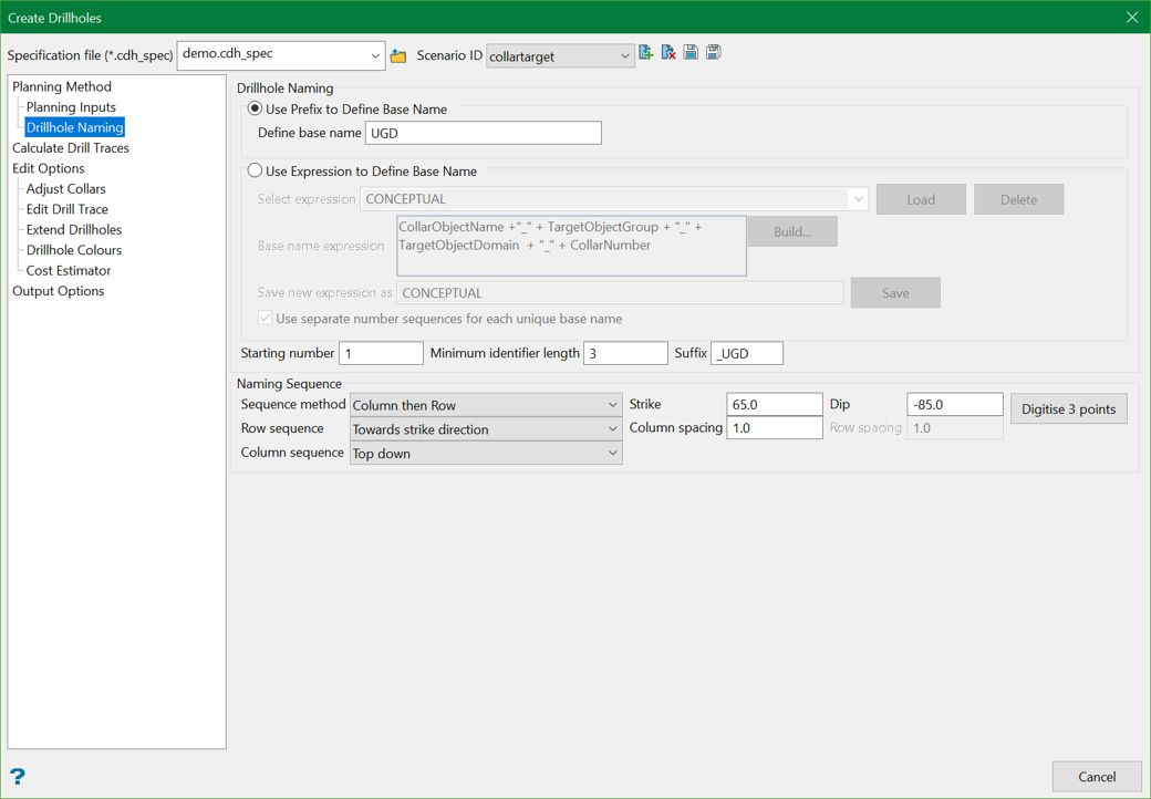
Use Prefix to Define Base Name
When creating drillholes in a production environment, generally a simple naming convention based on a prefix followed by a number is applied. This option is designed to utilise the value in the Define base name field as the prefix to be applied to the name of each drillhole.
Use Expression to Define Base Name
For conceptual drillhole planning purposes, a more complex naming convention is usually applied, which can incorporate several variables into the prefix applied to the drillhole name. This option provides an expression builder to allow the creation of complex prefixes based on input data and user-defined values.
Select expression
Select an existing expression from the DrillholePlanningName.spec file, stored in the Vulcan Resources folder. Once an existing expression has been selected, the Load button will populate the Base name expression field. The Delete button can be used to delete the selected expression from the DrillholePlanningName.spec file.
Base name expression
This field defines the variables and constants that will be used to create the Hole ID prefix. The expression can be populated from an existing expression in the DrillholePlanningName.spec file, from manually entered values, or by using the expression builder available on the click of the Build button.
In the example below, the expression builder has been utilised to create a conceptual drillhole naming expression (using the Collar and Target planning method) that is made up of the following parts, separated by underscores:
- The Object name of the input collar points,
- The Group value assigned to the input Target points (assigned when created in Create Drill Targets),
- The Domain values assigned to the input Target points (assigned when created in Create Drill Targets), and
- The collar index number (when an input line and spacing is used to generate the collar points, the collar index is generated sequentially down the line for each collar point).
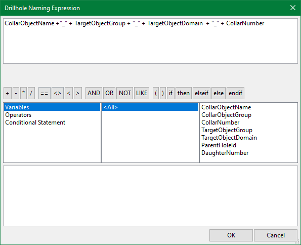
Example: An example of the output of the above expression would be 175_RD_TQ3_1.
Save new expression as
This allows the currently defined naming expression to be saved in the DrillholePlanningName.spec file. The expression can then be saved to the spec file by using the Save button on the right.
Use separate number sequences for each unique base name
For certain conceptual drillhole planning workflows, it may be desirable to have a separate number sequence for each unique base name; example, for each drill drive in the conceptual plan. This option will reset the number sequence back to the Starting number each time the base name changes. If this option was used in combination with the example expression above, the number sequence would be reset for each collar location as the CollarNumber has been used in the expression.
Starting number
The number that will be appended to the prefix of the first drillhole created. Subsequent drillholes will iterate from this starting number.
Minimum identifier length
This ensures that the Hole IDs contain the same number of characters. This applies zero-padding to the Starting number and subsequent iterated values to ensure that all Hole IDs contain the same number of characters.
Suffix
This is the suffix that will be added to the Hole IDs.
Naming Sequence
This determines the order in which the drillholes will be named. The naming sequence can follow one of the X, Y, or Z directions or the rows and columns of the planned holes.
Sequence method
This is the method used to determine the sequence order. One of the following methods can be chosen:
- Row then Column — Ordered working across the rows, column by column.
- Column then Row — Ordered working up or down the columns, row by row.
- X then Y — Ordered working up or down the X, Y by Y.
- X then Z — Ordered working up or down the X, Z by Z.
- Y then X — Ordered working up or down the Y, X by X.
- Y then Z — Ordered working up or down the Y, Z by Z.
- Z then X — Ordered working up or down the Z, X by X.
- Z then Y — Ordered working up or down the Z, Y by Y.
Row sequence
This option is available only if Row then Column or Column then Row is selected in the sequence method. This will have two values:
- Towards strike direction
- From strike direction
However, if any of the other sequence methods are selected, the options of X, Y, or Z sequence (referencing the values from the sequence method selected) are available with the following two values:
- Increasing
- Decreasing
Column sequence
This option is available only if Row then Column or Column then Row is selected in the sequence method. This will have two values:
- Top down
- Bottom up
However, if any of the other sequence methods are selected, the options of X, Y, or Z sequence (referencing the values from the sequence method selected) are available with the following two values:
- Increasing
- Decreasing
Strike
This is the strike orientation as defined for drillhole naming. This option is only applicable to Row then Column or Column then Row sequence methods. It can be entered manually or populated using the Digitise 3 points option.
Dip
This is the dip orientation as defined for drillhole naming. This option is only applicable to Row then Column or Column then Row sequence methods. It can be entered manually or populated using the Digitise 3 points option.
Digitise 3 points
Allows populating the Strike and Dip parameters by digitising 3 points to define a plane on screen, the first 2 points of which determine the strike and the 3rd point determines the dip.
Row spacing
This defines the height of a row in a grid. This would generally be defined based on the target spacing used when creating the drill targets.
Column spacing
This defines the width of a column in a grid that will label holes sequentially before moving to the next column. This would generally be defined based on the target spacing used when creating the drill targets.
Examples
Below is an example using the following settings:
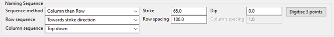
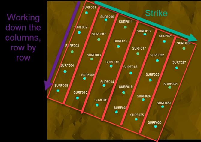
Figure 1 : Working down the columns, row by row
Below are some of the example diagrams of how the different naming sequence parameters affect the order of hole names, assuming strike direction is towards the right of screen.
Example 1
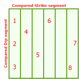
Figure 2 : Column then Row, Towards strike direction, Top down
Example 2
In this scenario, groups of holes have the sameCollar Object names (due to using drill drive line inputs to automatically calculate collar positions). The drillhole naming sequence will use the first drive name in the initial collar sorting sequence and name all holes sequentially for this drive, before moving to the next group of collars. This naming sequence is useful for generating sequential naming patterns for a drill rig to follow as it works down the drill drive when drilling the holes.
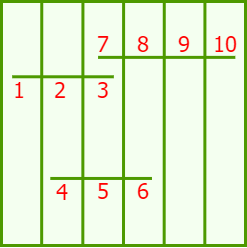
Figure 3 : Column then Row, Towards strike direction, Top down - when drill drives (collar line inputs or collar objects with the same Object Name) are used
Example 3
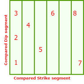
Figure 4 : Column then Row, Towards strike direction, Bottom up
Example 4
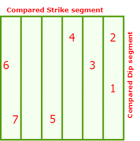
Figure 5 : Column then Row, From strike direction, Top down
Example 5
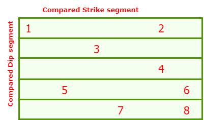
Figure 6 : Row then Column, Towards strike direction, Top down
Example 6

Figure 7 : Row then Column, From strike direction, Bottom up
Related Topics
- Evaluate Drill Density
- Create Drill Targets
- Create Drillholes
- Edit Drillholes
- Reporting
- Deviation Calculation Manager
- Drill Rig Setup Specification
- Cost Estimation Specification
- Reposition Hole
- Convert Object to Drillhole

