Drill Rig Setup Specification
Use this tool to create a specification file that can be used in the Create Drillholes or Edit Drillholes tools (for the Rig setup specification field in the Adjust Collars option) to quickly and easily adjust the collar positions to align with underground drill rig setup constraints provided by the drilling contractor.
This specification file stores a collar point matrix of dip and azimuth values, at the collar of the planned drillhole and the associated collar setup location.
Note: This help documentation takes an example of an underground mobile diamond drilling rig mounted on a jumbo carrier to serve as a reference guide. The MobileDiamondDrill.drs_spec file used in this example is available in the resources folder of your Vulcan installation.
Instructions
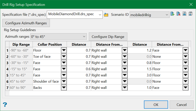
On the Geology menu, point to Drillhole Planning, then click Drill Rig Setup Specification to display the following panel.
Specification file
Use the drop-down list to select the specification file if it is in the current working directory, or browse for it in another location by clicking the Browse button. A new file may also be created by typing the name of the new file in the textbox.
Scenario ID
Use the drop-down list to select the ID file, or create a new one by clicking the New icon.
-
 New
New -
 Delete
 -
 Save
Save -
 Save as
Note: The specification file (*.drs_spec) is mandatory to run this tool and is used to store the setup constraints of a drill rig
Configure Azimuth Ranges
This button gets enabled only after a specification file is selected or created. Click on this button to display the grid editor panel below.
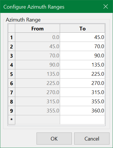
Use the grid to input the desired azimuth ranges, based on the drill rig setup constraints.
Important: Note that the azimuth values are azimuths relative to the strike of the development heading (i.e. the face) and not the actual azimuths of the drillholes.
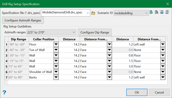
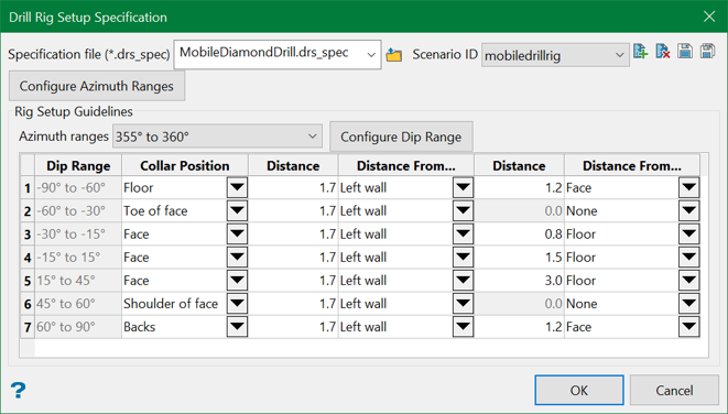
Rig Setup Guidelines
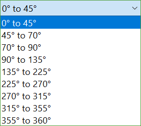
Azimuth ranges
Select the first of the configured azimuth ranges from the drop-down list.
Configure Dip Range
Click on this button to display the following grid editor panel.
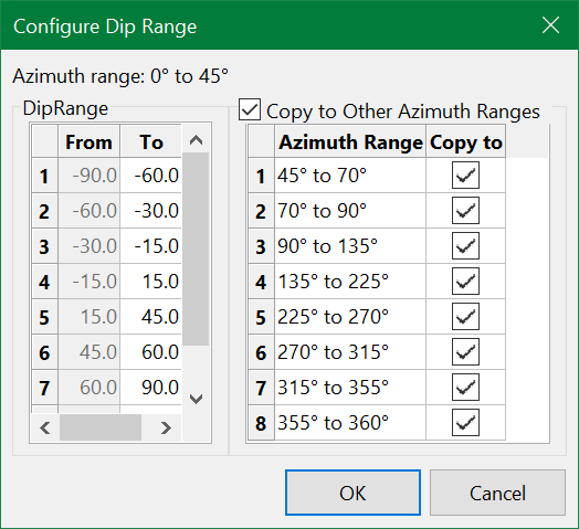
Use the grid to input the desired dip ranges, based on the drill rig setup constraints. The Copy to Other Azimuth Ranges option can then be used to copy the defined dip ranges to the desired azimuth ranges.
Once the azimuth and dip ranges have been defined, the main grid will be populated with default values. The default values can then be adjusted as required for the following parameters:
Collar Position
This is the final position of the collar if the drillhole azimuth and dip values at the collar falls into this bin in the matrix. The collar position can be one of the following:
- Floor
- Face
- Toe of face
- Shoulder of face
- Backs
- Wall
- Toe of Wall
- Shoulder of Wall
- N/A
Distance
This is the distance (as defined in the DG1) that the collar position must be placed from the corresponding Distance From… constraint.
Distance From…
The object from which the corresponding Distance constraint will be measured. This can be one of the following:
- Right wall
- Face
- Left wall
- Wall
- Floor
- None
Note: Up to two Distance/Distance From… constraints may be defined.
Example
SWICK jumbo carrier style underground diamond drill rig
Below is a matrix that cross-references the setup requirements, as defined by the dip and azimuth of the drillhole, for SWICK style underground diamond drill rigs that are mounted on jumbo carriers. Again, it is important to note that the azimuths are azimuths relative to the strike of the development heading (i.e. face) and not the actual drillhole azimuths. Below are some supporting diagrams for the collar point matrix that aid in the visualisation of the setup constraints and how this can be used as input to a drill rig setup specification.
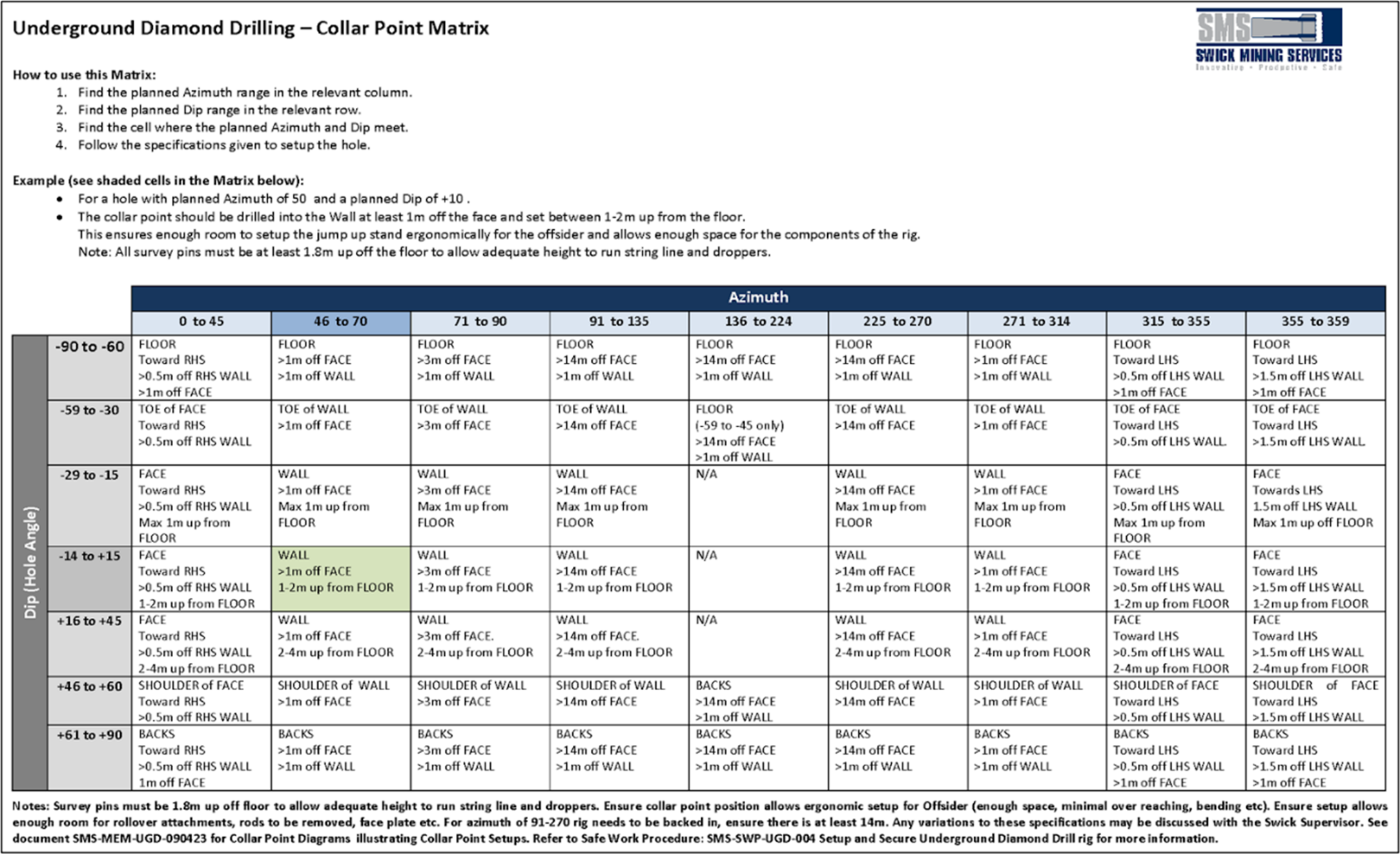
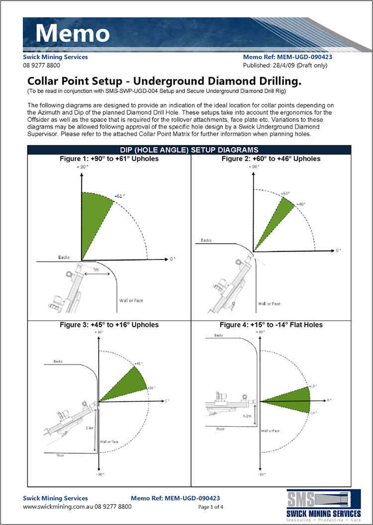
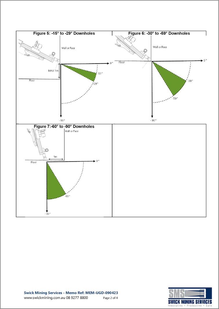
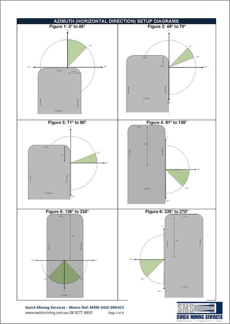
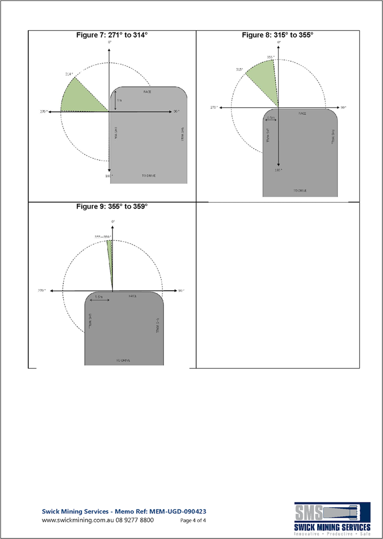
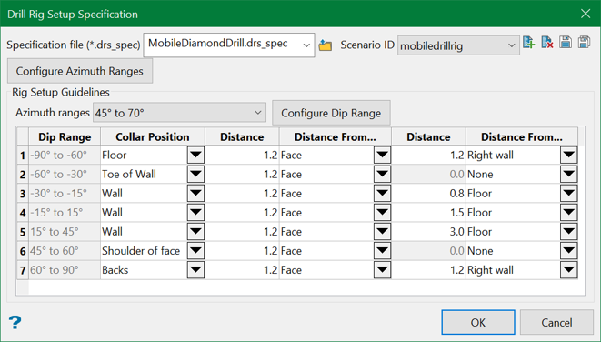
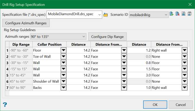
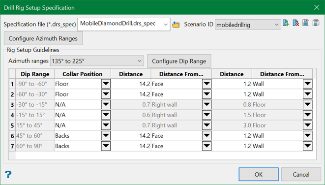
The above diagrams can be input into the specification file as shown below:


Related Topics
- Evaluate Drill Density
- Create Drill Targets
- Create Drillholes
- Edit Drillholes
- Reporting
- Deviation Calculation Manager
- Drill Rig Setup Specification
- Cost Estimation Specification
- Reposition Hole
- Convert Object to Drillhole

