Evaluate Drill Density
Use this option to evaluate the current density of the selected drillholes within a triangulation, based on user-defined distance ranges. This helps in identifying future drilling targets by highlighting gaps in current drilling.
Instructions
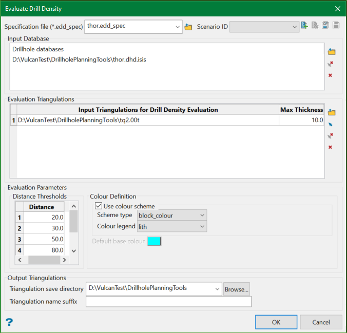
On the Geology menu, point to Drillhole Planning, then click Evaluate Drill Density to display the following panel.
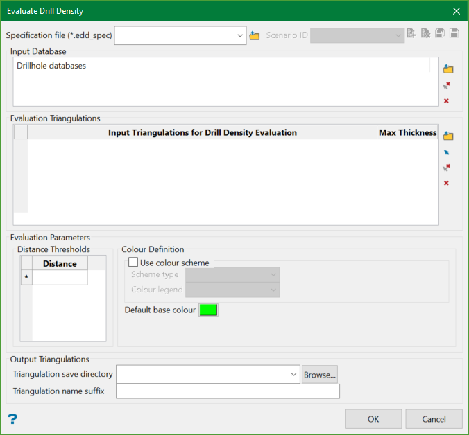
Specification file
Use the drop-down list to select the specification file if it is in the current working directory, or browse for it in another location by clicking the Browse button. A new file may also be created by typing the name of the new file in the textbox.
Scenario ID
Use the drop-down list to select the ID file, or create a new one by clicking the New icon.
-
 New
New -
 Delete
 -
 Save
Save -
 Save as
Note: The specification file is used to store the parameters used in performing a distance evaluation.
Input Database
Select one or more drillhole databases to be used in the drilling density evaluation. All drillholes in the selected databases will be considered for the distance evaulation. Use the Browse icon to select the desired databases and Clear icon to remove them from the list.
Note: If you want to filter the drillholes, it is advised to create a selection or filter file and load the desired drillholes into Vulcan first and then use Geology>Drilling Utilities>Create/Modify/Locate>Extract option to extract the loaded drillholes into a separate database.
Evaluation Triangulations
Select the desired triangulation(s) (both solids and surfaces are allowable) that will be used to evaluate the drill density within. Triangulations can be chosen by either browsing for the desired file from a folder or interactively selecting on the screen using the Screen Pick option from the controls on the right.
Max Thickness
An appropriate maximum thickness value must be defined for each of the selected triangulations. For solid triangulations, the Max Thickness refers to the true maximum thickness of the solid. For surface triangulations, the Max Thickness refers to the maximum expected height variance (undulation) across the surface, relative to the drillhole intersections with the surface.
Below is an example of how Max Thickness values of 5m and 10m would relate to the given surface and drillhole.
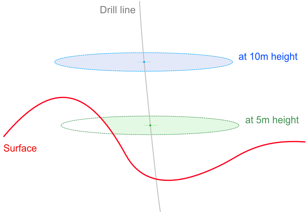
Figure 1 - Relation to a surface and drillhole for Max Thickness values of 5m and 10m
In the above instance, Max Thickness of 10m should be used as it is large enough to factor the undulation.
Important: The Max Thickness value is directly proportional to the processing time i.e. larger the value, longer the processing time. It is therefore advised to use an input value of slightly larger than the true thickness (for solids) or undulation (for surfaces) rather than using a large default value (like 999) in order to maximise the processing speed.
Evaluation Parameters
Distance Thresholds
The Distance Thresholds defines the diameters of the evaluation searches around each drillhole. This is a user-defined numeric input to set the cut-off bins to evaluate the drilling density. Eg. 20m, 30m, and so on.
Colour Definition
This allows selection of a predefined colour scheme that may have been created based on desired distance thresholds to be applied to the output triangulations. Alternatively, a default base colour may be selected for the first distance threshold from which subsequent colours will iterate.
Output Triangulations
The desired output directory may be selected for saving the output triangulations and an optional suffix can be applied to the name of the output triangulations to categorise them.
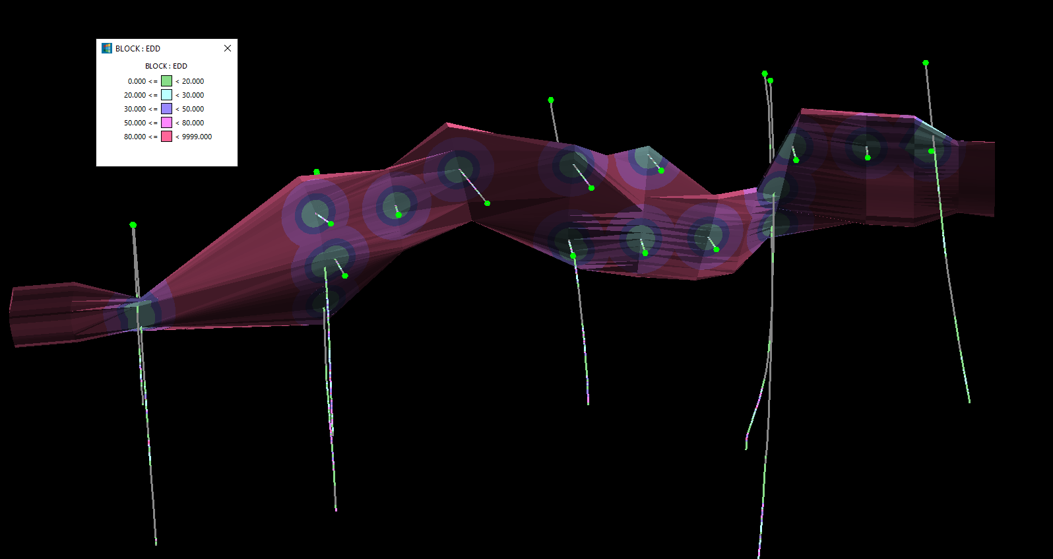
Outputs
Non-overlapping (mutually exclusive) valid triangulation solids or surfaces for each evaluation bin are named according to the input triangulation, distance threshold, and user suffix.
During the distance evaluation process, a series of cylinders are created around each drillhole intersection mid-point with the input triangulation for each distance threshold. These cylinders are oriented such that they align perpendicular to a pseudo mid-surface (as shown in Figure 2), in the case of a solid input, and are booleaned against the input solid. If a surface is used as the input triangulation, the cylinders are created perpendicular to the input surface. This logic has been applied in order to reflect the drilling density at the mid-point of a solid triangulation and reduce the impact of sub-optimal angled drillhole intersections.
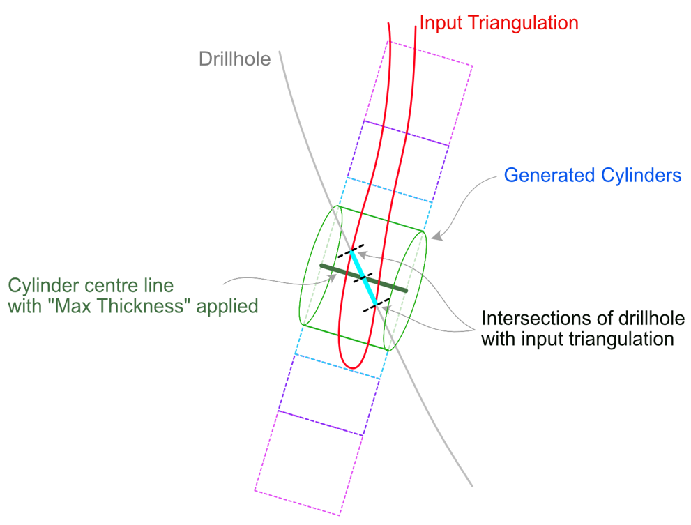
Figure 2 - Distance evaluation process
In some special scenarios, for example where a solid triangulation folds back on itself and a drillhole intersects perpendicular to the fold hinge, the output may not be exactly as expected. In this case, it is advised to first create a mid-surface (using the Create Drill Targets tool to generate mid-points of surface) and use the mid-surface to perform the distance evaluation. Another alternative would be to split the input triangulation into two separate solids at the fold hinge before running the distance evaluation.
In a scenario, as shown in Figure 3, where there are 3 intersection points with the drillhole and the input triangulation, the third intersection point would be disregarded.
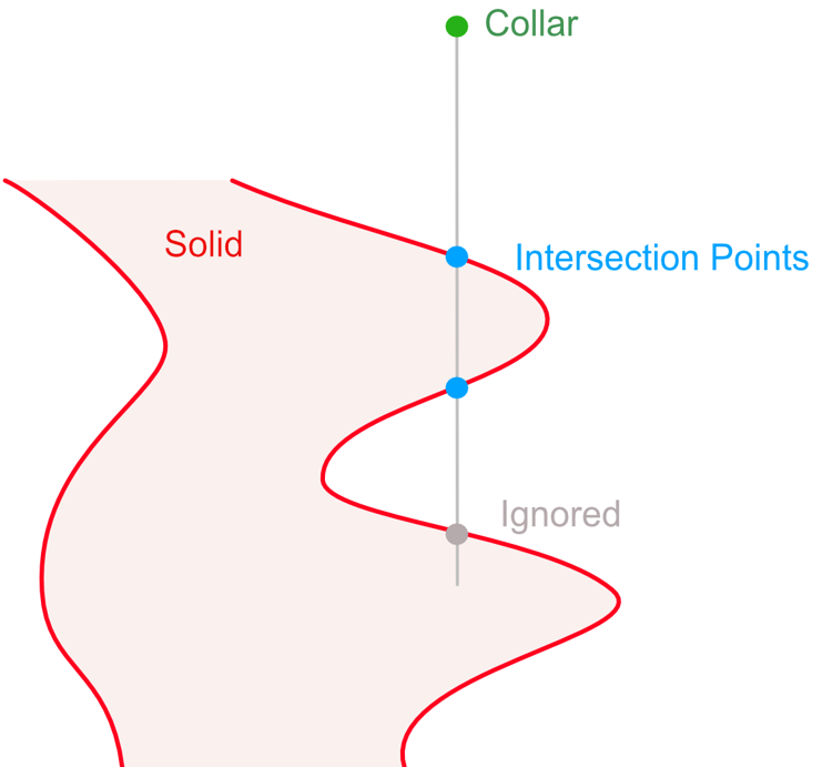
Figure 3 - Three intersection points with drillhole and input triangulation
Example - Input vs Output
The example below shows the input settings selected and the corresponding output produced.
Input
Output
Related Topics
- Evaluate Drill Density
- Create Drill Targets
- Create Drillholes
- Edit Drillholes
- Reporting
- Deviation Calculation Manager
- Drill Rig Setup Specification
- Cost Estimation Specification
- Reposition Hole
- Convert Object to Drillhole

