Planning Method
This section defines the type of drillholes that will be designed.
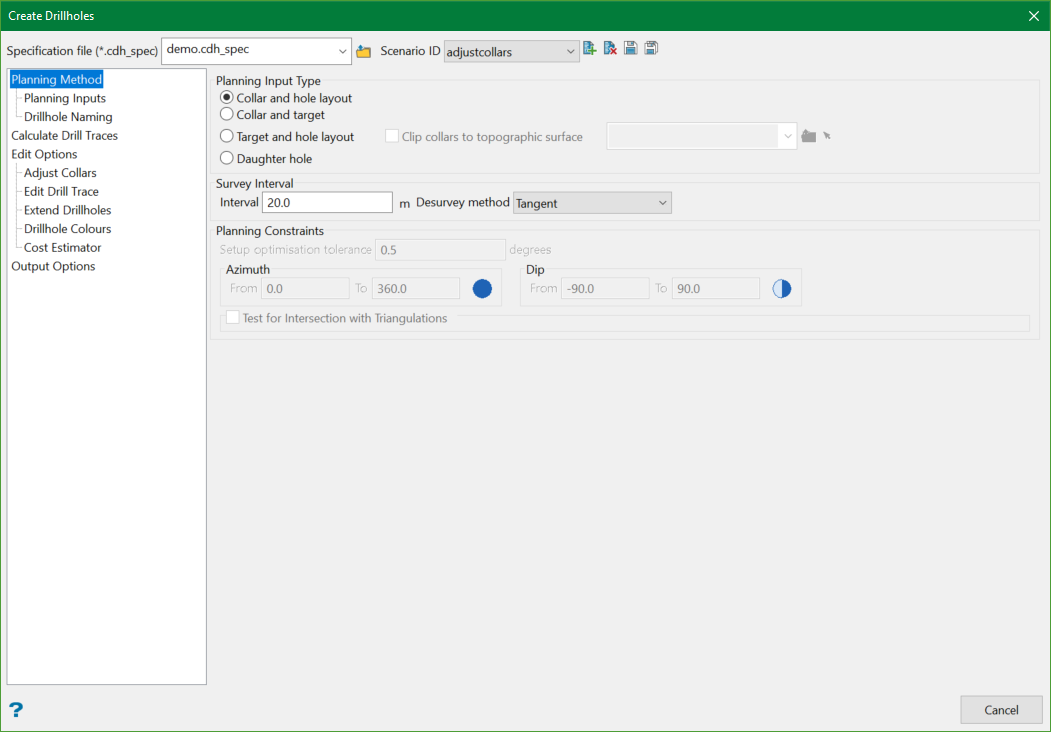
Planning Input Type
The type selected here determines the options that will be available in the subsequent sections on the panel. There are four types of planning inputs:
Collar and hole layout
This method allows drillholes to be created using collar location(s) and collar dip, azimuth, and hole length parameters.
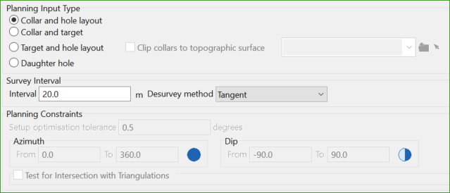
Survey Interval
This creates survey points down the hole at the specified interval, which is to be used when applying deviation to the drill trace. This applies for all the planning methods.
Desurvey method
There are two methods available to give azimuth and dip values at various depths down the hole. To know more, see Desurvey style.
-
Segment Following: In this method, the azimuth and dip describes the drillhole interval following the given depths.
-
Tangent: In this method, the azimuth and dip occur at the given depths. This means that they describe the tangent at that point of the drill hole.
For details, go to Planning Inputs.
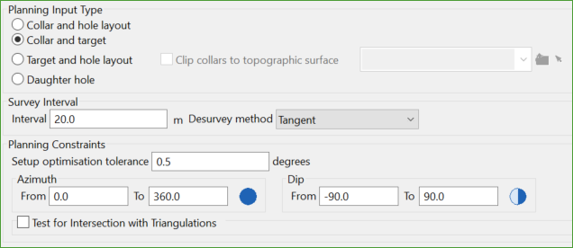
Collar and target
The method utilises the collar and target locations, which will determine the hole layout parameters. The targets can be created using the Create Drill Targets tool.
If the default planning constraints to control azimuth and dip are unchanged, the drillhole creation methodology when creating multiple drillholes, is the shortest distance from collar to target. If azimuth and/or dip planning constraints other than the defaults are defined, the methodology is the shortest distance that satisfies these planning constraints first. If a drillhole is unable to satisfy the planning constraints, then the hole that most closely resembles the planning constraints will be created and details will be printed to the Vulcan Console.
Planning Constraints
These are constraints used to control the orientation of drillholes created using this planning method.
Setup optimisation tolerance
This defines the tolerance (in degrees) for the optimisation of collar azimuth and dip values when applying deviation to drillholes.
When designing curved drillholes, the dip and azimuth at the collar will automatically be adjusted to account for the selected deviation rates while allowing the hole to pass as close to the target as possible, given the Setup optimisation tolerance value.
A tolerance of 0.5 degrees, typically the limit of accuracy within which a drill rig can be set up, is recommended. With a practical value such as 0.5, it is expected that the planned drillhole will not exactly intersect the planned target.
When determining the optimal collar dip and collar azimuth values, the initial values are rounded to the nearest integer, then incremental values plus or minus the Setup optimisation tolerance are tested, and the values that provide the lowest calculated distance to target (the shortest distance from the target to the drill trace) are selected.
Azimuth
This defines the desired azimuth range to create drillholes within.
Dip
This defines the desired dip range to create drillholes within.
Test for Intersection with Triangulations
This option is used to allow exclusion zones to be included while the drillholes are being planned.
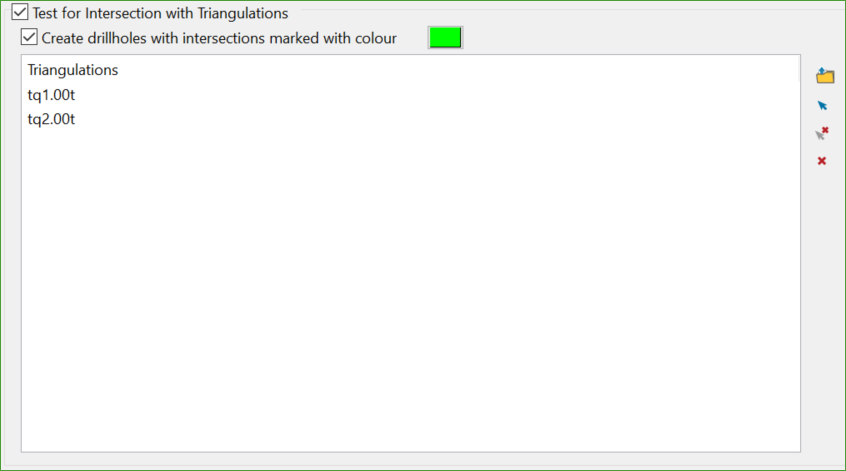
Selecting this option will enable the tool to test if any of the drillholes created using the planning constraints intersect the selected triangulation(s). If they do, the tool still allows to create drillholes with intersections but have them colour differently so that users can later manually change the collar position from the Adjust Collars panel to correct the intersection.
Creating drillholes with intersections marked with colour
This option allows user to select the colour for the drillholes with intersections.
Note: This option will take precedence over other planning constraints.
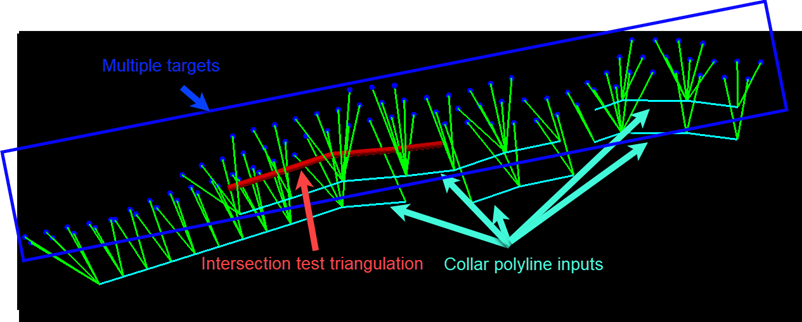
Figure 1 : Test for intersection with triangulations
For details, go to Planning Inputs.
Target and hole layout
This method allows drillholes to be created using target locations and collar dip, azimuth, and hole length parameters.
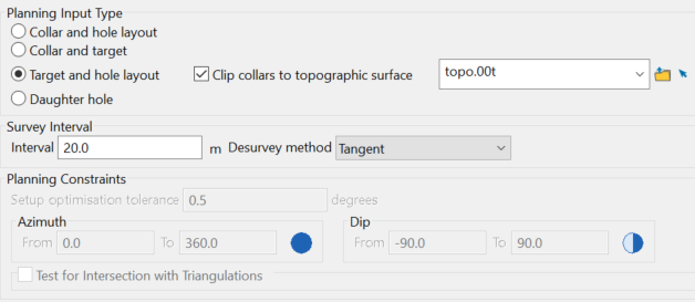
In this scenario, the hole layout is defined from the collar, such that the values input into the Hole Layout are essentially reversed, creating the collar by projecting back up from the target. This type of scenario can be used to determine the location of a surface drill pad that can intersect the desired target.
Clip collars to topographic surface
This option will relimit any drillholes that extend beyond the selected topographic surface, due to their designed Hole length in the Planning Inputs section.
Below is an example:
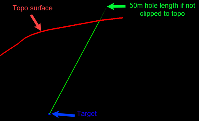
Figure 2 : Clipping collars to topographic surface
For more details, go to Planning Inputs.
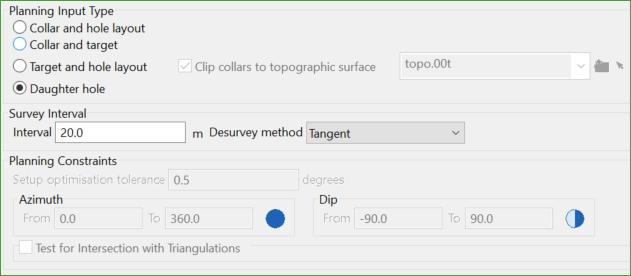
Daughter hole
This method allows wedge drillholes to be created from a selected existing parent drillholes.
For more details, go to Planning Inputs.
Related Topics
- Evaluate Drill Density
- Create Drill Targets
- Create Drillholes
- Edit Drillholes
- Reporting
- Deviation Calculation Manager
- Drill Rig Setup Specification
- Cost Estimation Specification
- Reposition Hole
- Convert Object to Drillhole

