Planning Method
This section defines the parameters for the type of drillholes that have been designed previously and will be imported into the tool for editing. Defining these parameters correctly is important, as this is how the editable attributes are calculated.
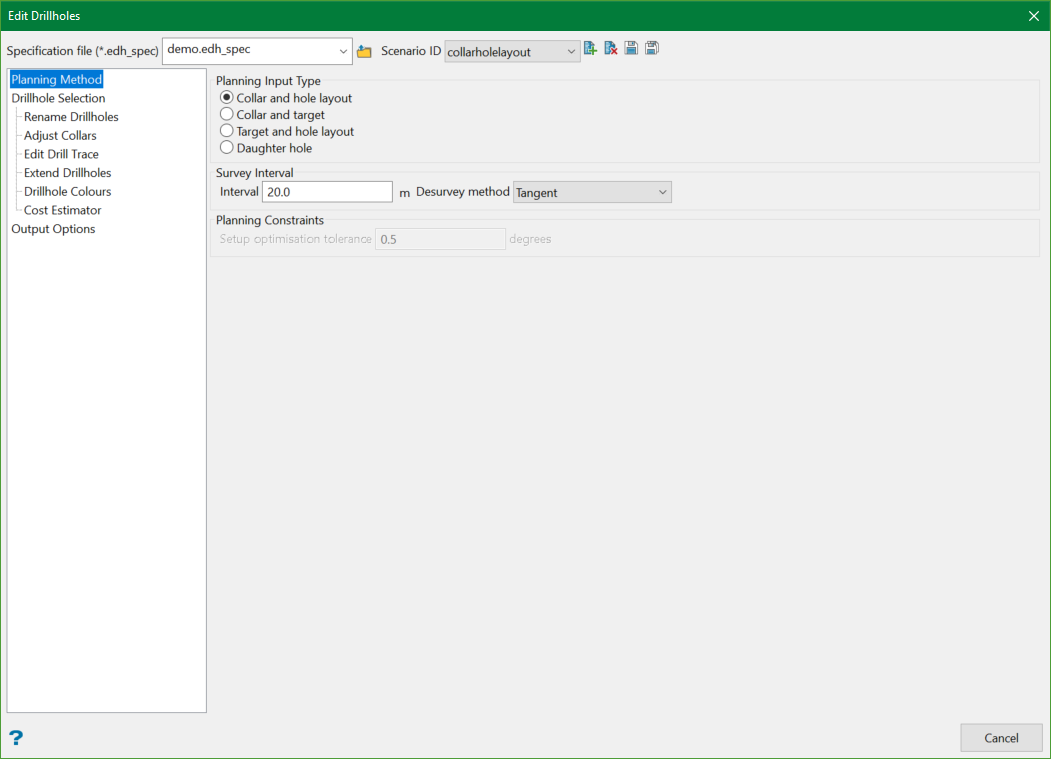
Planning Input type
Collar and hole layout
This method allows editing of drillholes using collar location(s) and collar dip, azimuth, and hole length parameters.
Collar and target
The method allows editing of drillholes created using collar and target locations, which determined the hole layout parameters.
Target and hole layout
This method allows editing of drillholes created using target locations and collar dip, azimuth, and hole length parameters.
Daughter hole
This method allows editing of wedge drillholes from a selected existing parent drillholes.
Survey Interval
This creates survey points down the hole at the specified interval, which is to be used when applying deviation to the drill trace. When drillholes are imported, if they are CAD drillholes created using the Create Drillholes tool, then the existing survey information will be imported from the drillholes otherwise the Survey Interval value will be used to create the drill traces.
Desurvey method
There are two methods available to give azimuth and dip values at various depths down the hole.
-
Segment Following: In this method, the azimuth and dip describes the drillhole interval following the given depths.
-
Tangent: In this method, the azimuth and dip occur at the given depths. This means that they describe the tangent at that point of the drill hole.
To know more, see Desurvey style.
Planning Constraints
These are constraints used to control the orientation of drillholes created using the Collar and target planning method.
Setup optimisation tolerance
This defines the tolerance (in degrees) for the optimisation of collar azimuth and dip values when applying deviation to drillholes.
When designing curved drillholes, the dip and azimuth at the collar will automatically be adjusted to account for the selected deviation rates while allowing the hole to pass as close to the target as possible, given the Setup optimisation tolerance value.
A tolerance of 0.5 degrees, typically the limit of accuracy within which a drill rig can be set up, is recommended. With a practical value such as 0.5, it is expected that the planned drillhole will not exactly intersect the planned target.
When determining the optimal collar dip and collar azimuth values, the initial values are rounded to the nearest integer, then incremental values plus or minus the Setup optimisation tolerance are tested, and the values that provide the lowest calculated distance to target (the shortest distance from the target to the drill trace) are selected.
Related Topics
- Evaluate Drill Density
- Create Drill Targets
- Create Drillholes
- Edit Drillholes
- Reporting
- Deviation Calculation Manager
- Drill Rig Setup Specification
- Cost Estimation Specification
- Reposition Hole
- Convert Object to Drillhole

