Create Drill Targets
Use this tool to quickly and easily create drilling target points within a triangulation based on user-defined grid spacings. These target points can later be used as input to creating drillholes.
Instructions
On the Geology menu, point to Drillhole Planning, then click Create Drill Targets to display the following panel.
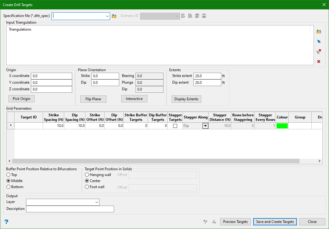
Specification file
Use the drop-down list to select the specification file if it is in the current working directory, or browse for it in another location by clicking the Browse button. A new file may also be created by typing the name of the new file in the textbox.
Scenario ID
Use the drop-down list to select the ID file, or create a new one by clicking the New icon.
-
 New
New -
 Delete
 -
 Save
Save -
 Save as
Note: The specification file is used to store the parameters used in creating drilling targets.
Input Triangulation
Select one or more triangulations to be used in creating the output target points. Use the Browse icon to select the desired databases and Clear icon to remove them from the list.
Origin
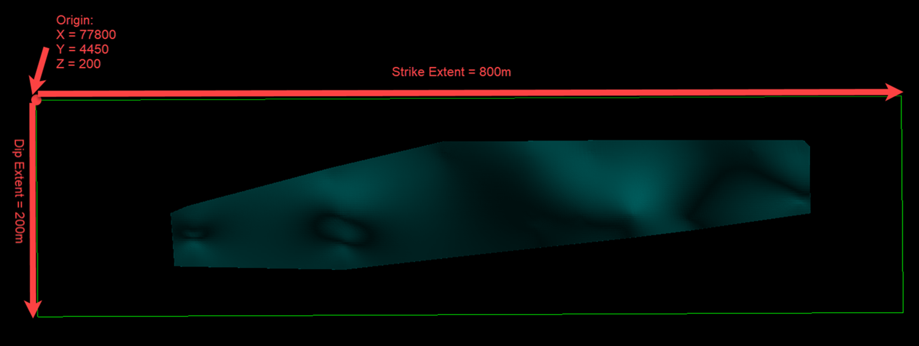
This is the corner of the extents used to create target points. The dip and strike extents extend out from this origin point. For example, an origin at the top left will result in a positive dip value dipping downwards.
Pick Origin
This option allows the origin to be defined by manually digitising a position on screen. You can pick from the screen the corner of the extents to create target points.
Plane orientation
Based on the inputs from the Grid Parameters , this section defines the orientation of an extents plane on which to build the grid(s). The extents plane can be oriented to align with the geology in order to ensure that the appropriate drilling target density is achieved.
Strike
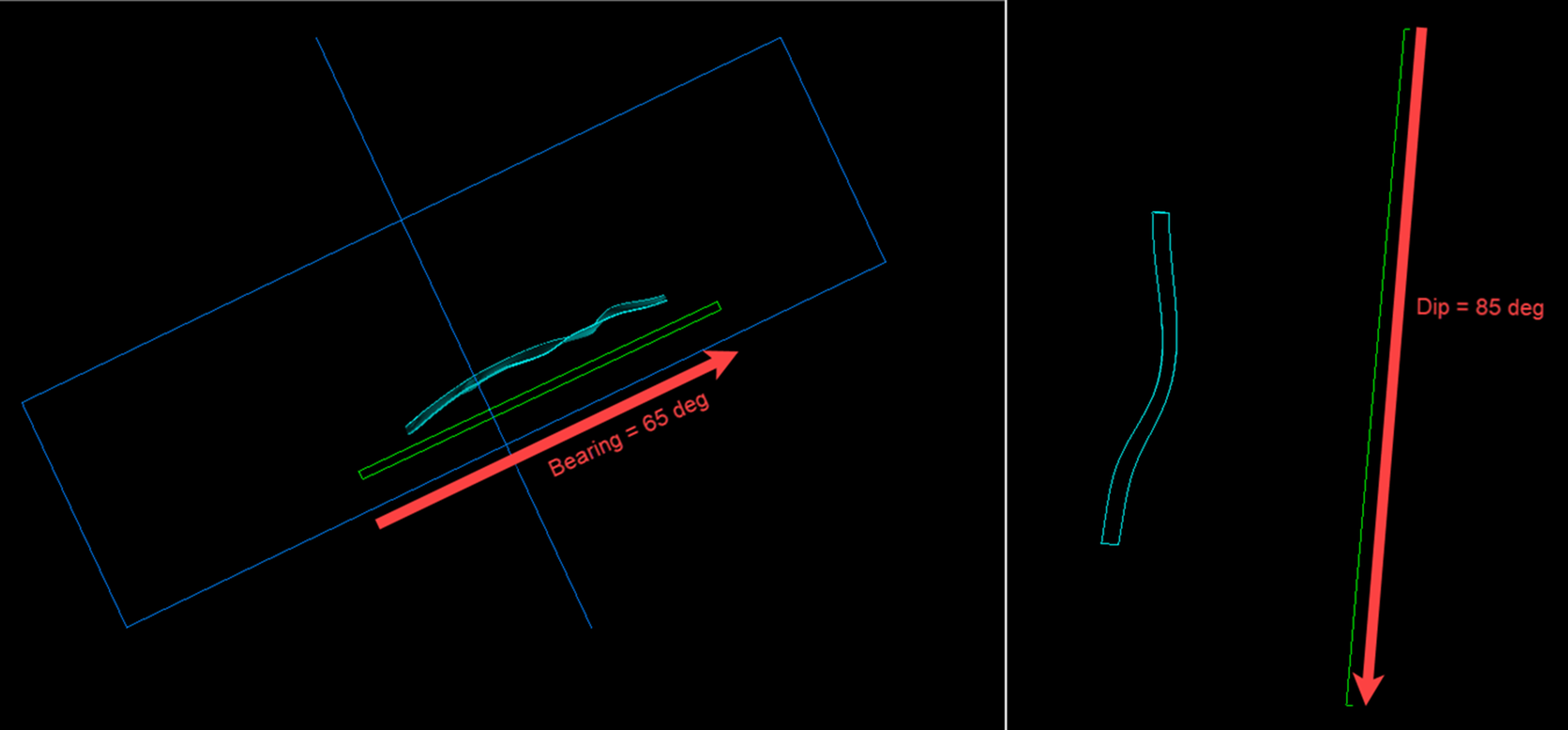
This is the direction (in degrees) from the origin that determines the direction of the strike extents.
Dip
This is the direction (in degrees) from the origin that determines the direction of dip extents. You can enter only values between 0-90 degrees. The default value is 90 degrees, which means that the dip extents will be projected vertically downward from the origin.
Bearing
This is a value set by the interactive ellipsoid control to define the orebody orientation. The strike and dip of the planes are calculated from these values.
Note: Bearing may not always be the same as the strike as this can be affected by any plunge that may be applied to the plane.
Plunge
The is the value of plunge (in degrees) from the origin as defined by the interactive ellipsoid control.
Dip
The is the value of dip (in degrees) from the origin as defined by the interactive ellipsoid control.
Note: The dip value may not always be the same as the value in the Dip input as this can be affected by any plunge that may be applied to the plane.
Flip plane
The orientation of the extents plane can be reversed using this option. It flips the extents plane 180 degrees around the strike extents axis.
Example: For a strike of 0 degrees and a dip of 90 degrees, the Flip plane button flips the extents plane such that the plane is dipping vertically upwards from the origin.
Interactive
This option allows to define more complicated plane orientation by the use of an interactive ellipsoid editor.
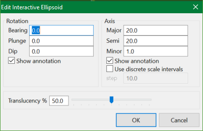
Example: For a strike of 0 degrees and dip of 45 degrees, it creates an extents plane dipping towards the west. However, if you want an extents plane dipping towards the east, enter a dip value of 135 degrees (i.e. 180 - 45) on the interactive ellipsoid panel.
Extents
This is the extent settings to define the region in which the target points are to be created. This allows the targets points to be restricted to a portion of the triangulation rather than filling the whole triangulation with targets.
Strike extent
The is the distance (in project units) from the origin along the strike to define the extents.
Dip extent
This is the distance (in project units) from the origin along the dip to define the extents.
Display/Hide Extents
This is a toggle button to display or hide the extents box. The extents box is dynamic and will automatically update to reflect the changes made to the origin, orientation, and extents inputs.
Example - The green box represents the outline the Display Extents option would show as per the parameters defined in the figures below.
Grid Parameters
These parameters are used to define the spacing and alignment of the desired target grid(s).
TargetID
This is a reference identifier for the target type, which is a user-defined alphanumeric field.
Strike Spacing
This is the desired spacing (in DG1 distance units) of the target points along the strike direction.
Dip Spacing
This is the desired spacing (in DG1 distance units) of the target points along the dip direction.
Strike Offset
This is the desired offset distance along the strike, relative to the origin, to start creating target points. It can be useful to start a grid at a particular coordinate location within the triangulation.
Dip Offset
This is the desired offset distance along the dip, relative to the origin, to start creating target points. It can be useful to start a grid at a particular coordinate location within the triangulation.
Strike Buffer Targets
This is an integer input field that determines the number of target points that can be created outside the triangulation (along the trajectory of the target points). It can be useful for including targets to test the extent of the ore domain.
Dip Buffer Targets
This is an integer input field that determines the number of target points that can be created outside the triangulation (along the trajectory of the target points). It can be useful for including targets to test the extent of the ore domain.
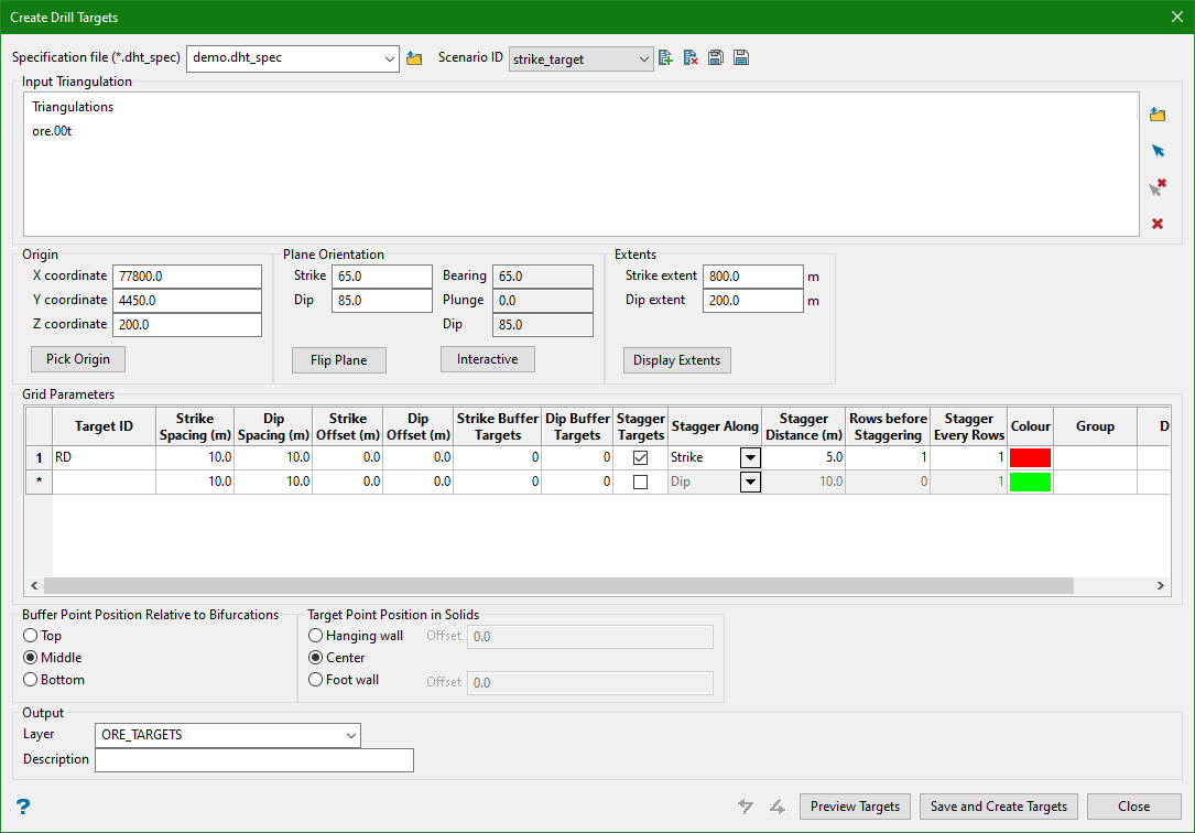
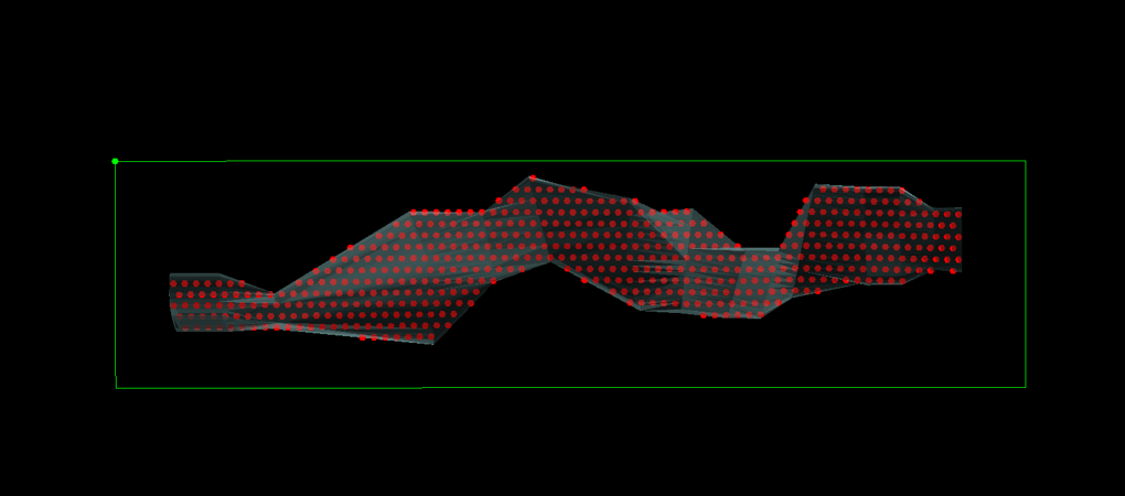
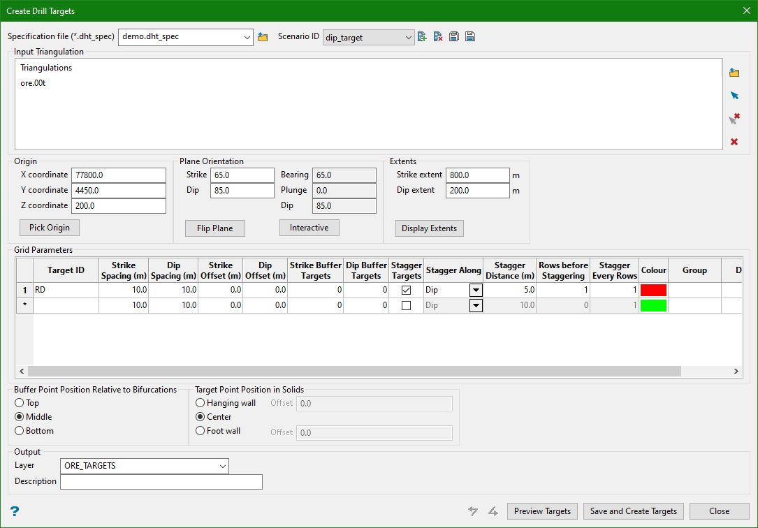
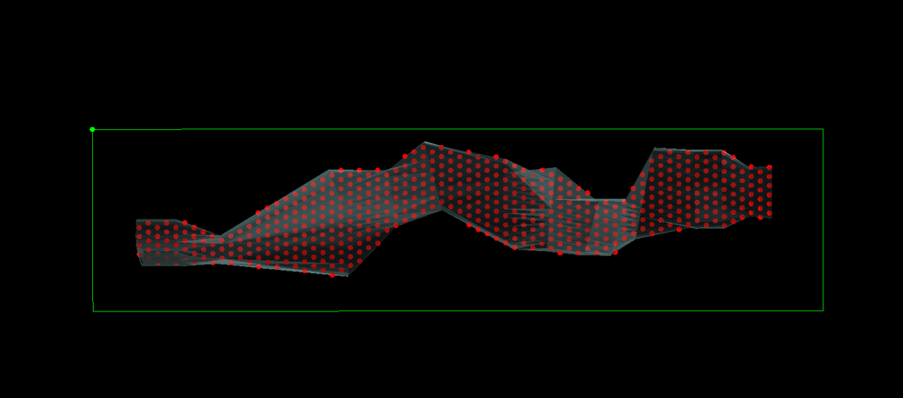
Stagger Targets
This option allows to stagger target points between rows. If unchecked, all other Stagger fields are disabled.
Stagger Along
This is a drop-down box with two options, namely Dip and Strike. It allows users to stagger the target points either along the dip or the strike.
Stagger Distance
This is a distance input field (in DG1 distance units) that determines the distance from which the target points can be staggered along the selected direction.
Rows Before Staggering
This is an integer input field, which determines the number of rows that can be created before staggering the next row of points.
Stagger Every Rows
This is an integer input field, which determines how often the stagger pattern repeats.
Colour
Use this option to define the colour of all the target points created with the TargetID.
Group
Use this option to flag the group of all targets created with the TargetID.
Domain
This is an alphanumeric value which allows to flag the attribute of the target points called 'Domain'.
Buffer Point Position Relative to Bifurcations
If a bifurcation exists at the extent of a triangulation, buffer points can be created at different positions.
Note: This is only applicable to buffer points.
Top
Choose this option to create buffer points in the first limb of the bifurcation.
Middle
Choose this option to create buffer points in between the limbs of the bifurcation.
Bottom
Choose this option to create buffer points in the second limb of the bifurcation.
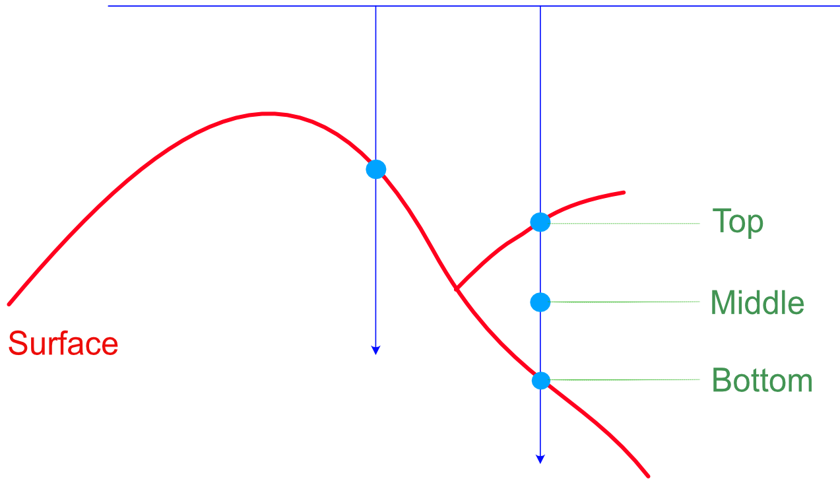
Figure 1- Difference of output for buffer point positive relative to bifurcations (on the edge of triangulation)
Target Point Position in Solids
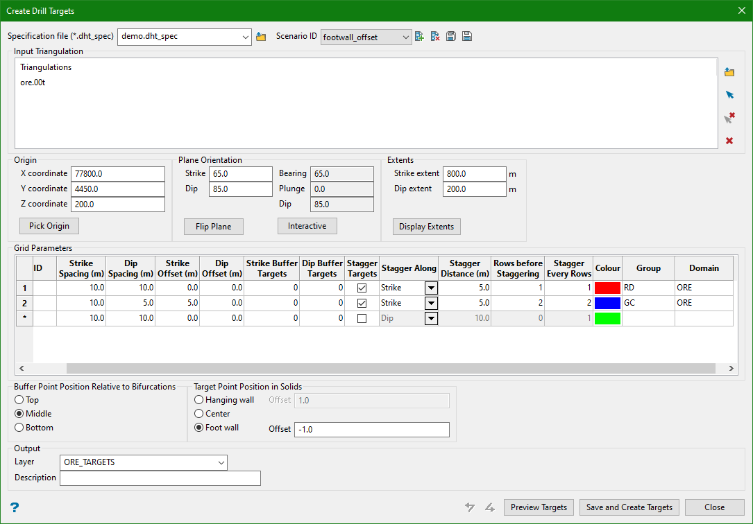
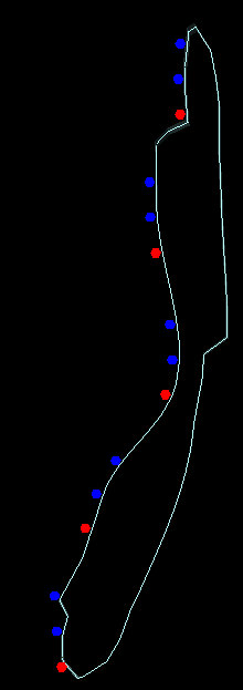
Targets within solids can be created on the hanging wall, foot wall, or in the centre of the solid. An offset distance can be specified to offset the points from the hanging wall or foot wall. Positive offset values offset inside the solid while negative values offset outside of the solid.
Note: Hanging wall (HW) and foot wall (FW) are defined by their relationship to the extents plane, such that the hanging wall represents the side of the triangulation closest to the plane.
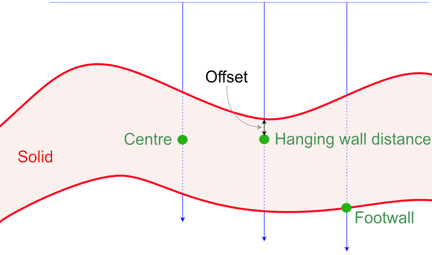
Figure 2 - Difference of output for target point position in solids
Outputs
The output of the drill targets is a CAD layer with points (individual objects for each target point). A layer name must be provided and an optional description may be added if desired.
In the case of a solid triangulation input, the points need to be created in the middle of the solid (i.e. half way between the hanging wall and foot wall facets). In the case of a surface, the points are created on the surface.
Preview Targets
When Preview Targets is pressed, the targets generated from the inputs will be displayed on the screen.
Note: Each time this button is pressed, a snapshot of the panel settings is created and added to the Undo/Redo history list.
Examples - Input vs Output
The examples below show the input and the corresponding output produced against different input values.
1. Simple
Input
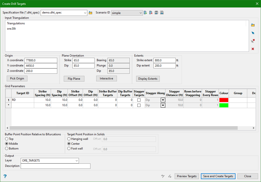
Output
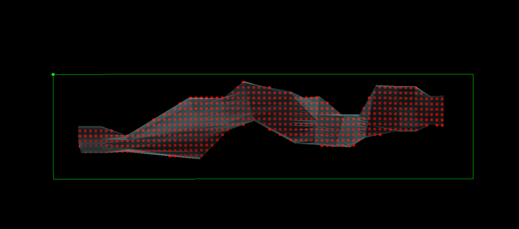
2. Strike Buffer
Input
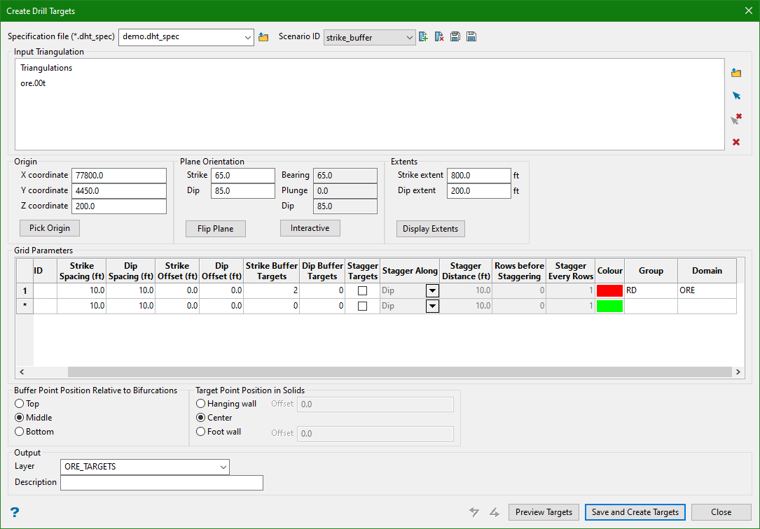
Output
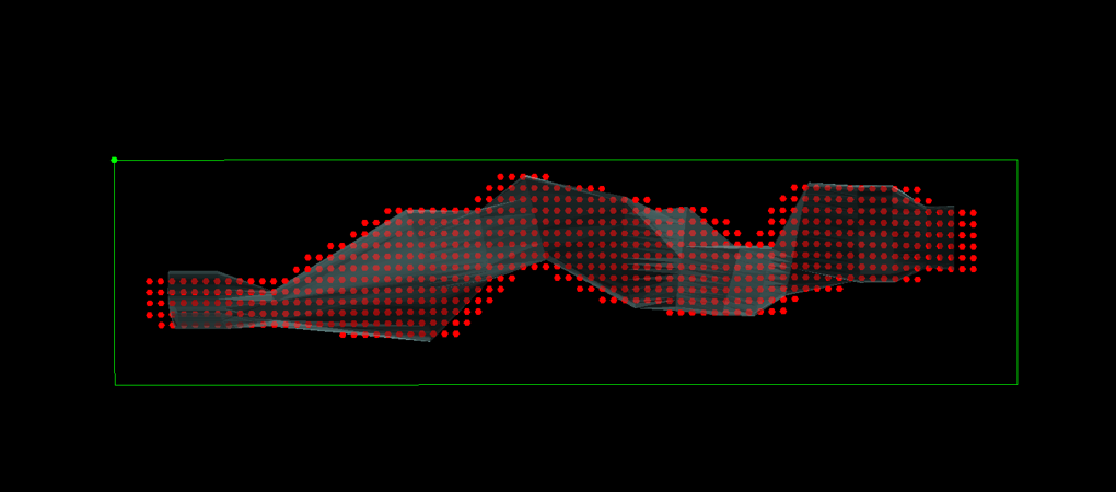
3. Dip Buffer
Input
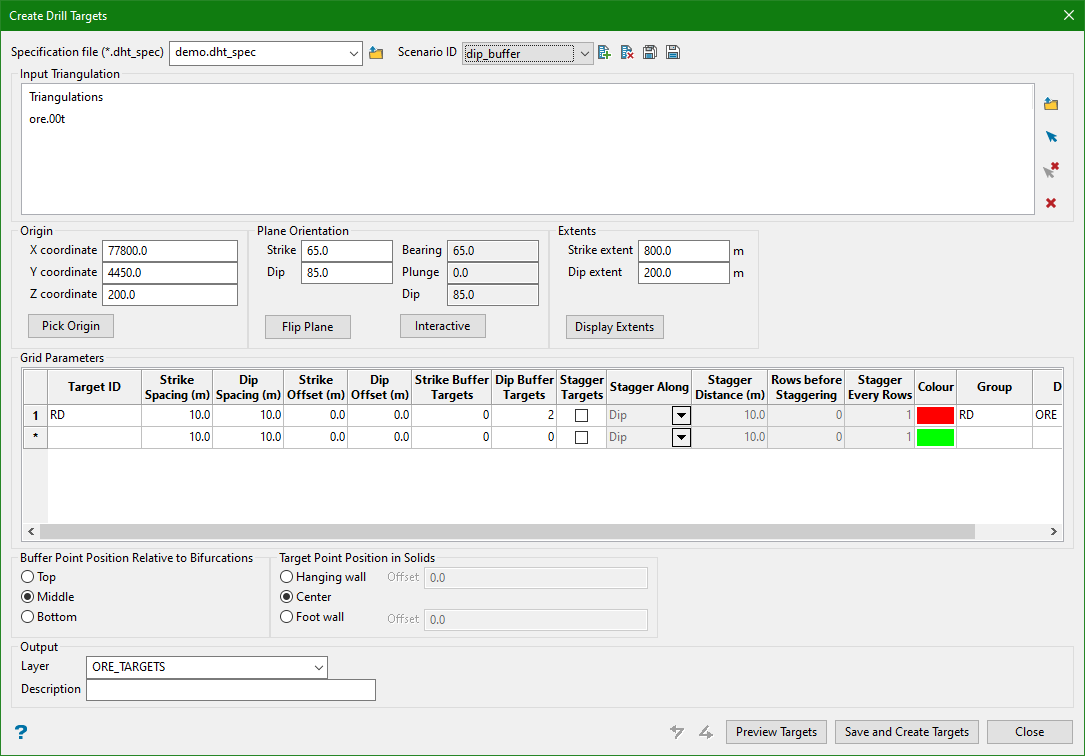
Output
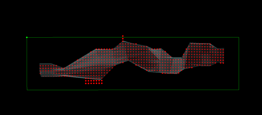
4. Strike Stagger
Input
Output
5. Dip Stagger
Input
Output
6. Complex Diced 5 Pattern
Input
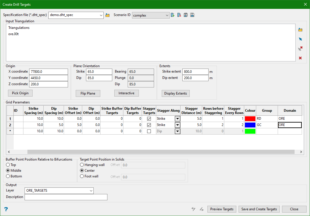
Output
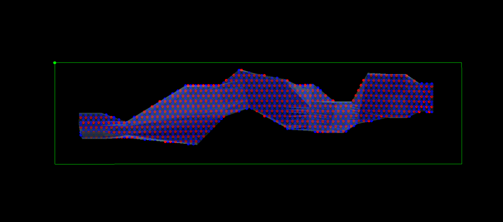
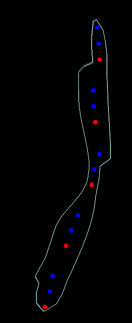
7. Points on Hanging Wall
Input
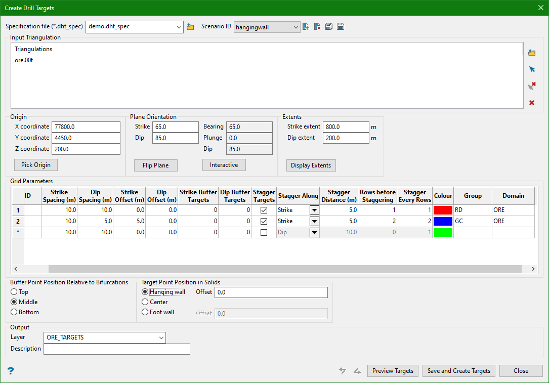
Output
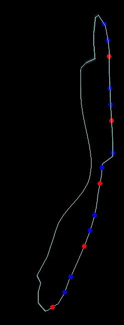
8. Points on Hanging Wall with Positive Offset
Input
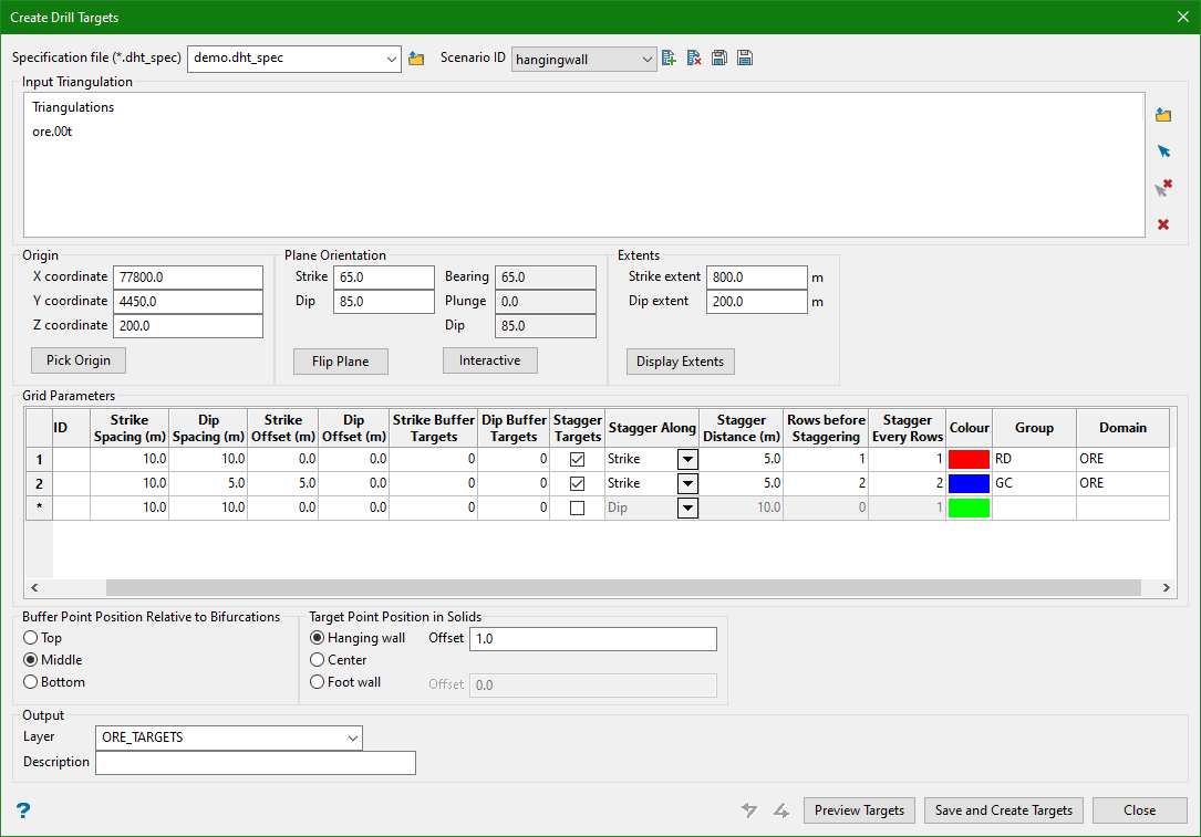
Output
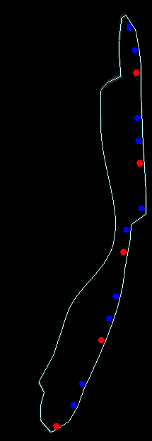
9. Points on Foot Wall
Input
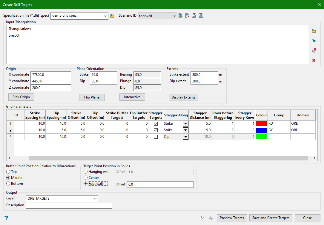
Output
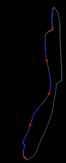
10. Points on Foot Wall with Negative Offset
Input
Output
Related Topics
- Evaluate Drill Density
- Create Drill Targets
- Create Drillholes
- Edit Drillholes
- Reporting
- Deviation Calculation Manager
- Drill Rig Setup Specification
- Cost Estimation Specification
- Reposition Hole
- Convert Object to Drillhole

