Solid Cuts
Solid cuts in Epoch divide dynamic solids models in your Epoch setup into smaller sections, allowing you to adjust the area of mining to match the operations scheduled for each period.
Evolution supports the following cutting methods:
-
 Direct Cut: Define precise cut lines manually in the viewer. This cutting method is suitable for precise geometric control, including cutting along geologic boundaries or mining phases. See Direct Cut for more information.
 -
 Target Seeking Cut: Perform solid cuts by specifying target quantities. This cutting method is used for operational planning, where specific production targets (for example, targets set for each shift, daily or weekly plans) need to be achieved. See Target Seeking Cut for more information.
 -
 Simple Cut: Perform simple solid cuts by specifying the target mass accumulation and the direction in which you want the mining to proceed. See Simple Cut for more information.
Important: As solid cuts require the underlying block model to reserve the attributes for the solids, the cutting feature is only available in dynamic solids models. See Dynamic Solids Pits and Importing a Dynamic Solids Pit for more information.
Tip: Use the viewer guidelines feature to determine where to make solid cuts. For example, if you have Vulcan design database (.dgd.isis) or Vulcan archive (.arch_d) files with grade control polygons (marked out regions that group areas of similar grade), you can use them to identify which regions of the pit or on a certain bench should be scheduled. See Viewer guidelines for more information.
Tip: Apply material grade-based colour bands to your dynamic solids models to determine the best locations to perform solid cuts. Keep the ![]() (Shrink Blocks) feature (that is available in the viewer toolbar only for dynamic solids models) enabled for best visibility of your model. See Add Colour Bands and Dynamic colour in Epoch for more information.
(Shrink Blocks) feature (that is available in the viewer toolbar only for dynamic solids models) enabled for best visibility of your model. See Add Colour Bands and Dynamic colour in Epoch for more information.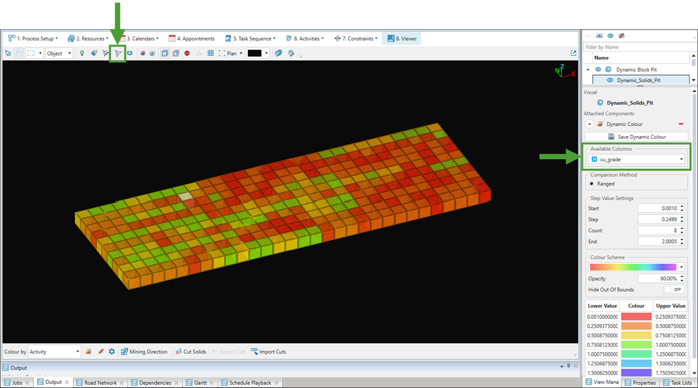
See Common features for more information and tips on common features that you can use while navigating through solid cuts.
Accessing solid cutting feature
You can access the solid cutting feature the following ways:
-
Click the
 Cut Solids button in the viewer.
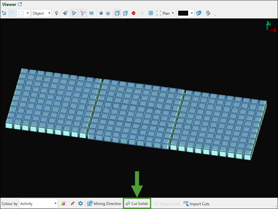
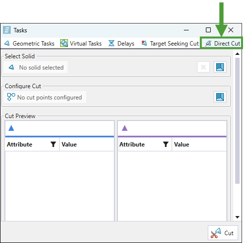
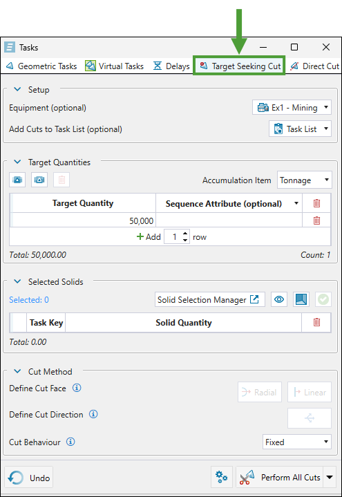
The Tasks panel will appear with the
Target Seeking Cut tab open by default. Stay in this tab or switch to the Direct Cut tab as required.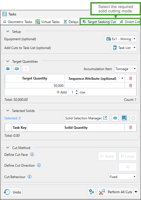
-
Enter from the Task Lists tab in the viewer.
To do so, navigate as follows:
-
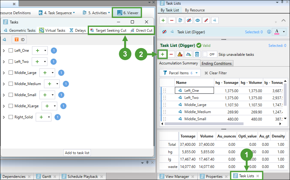
Open the Task Lists tab in the viewer.
-
Click
 (Add task list).
 -
Select the required solid cutting mode in the Tasks window.
-
Note: Unlike the ![]() Direct Cut and
Direct Cut and ![]() Target Seeking Cut, the
Target Seeking Cut, the ![]() Simple Cut feature can only be entered from the context menu in the viewer. To enter this solid cutting method, right-click on the required solid in the viewer and select
Simple Cut feature can only be entered from the context menu in the viewer. To enter this solid cutting method, right-click on the required solid in the viewer and select ![]() Simple Cut.
Simple Cut. 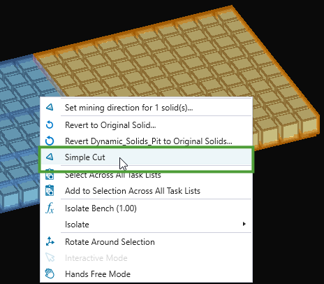
See Simple Cut for more information.
Direct Cut
The direct cut feature in Epoch allows you to define precise cut lines manually in the viewer. As you specify the cut lines, Evolution will provide the preview of the resulting solids and calculate their attributes in real time.
Tip: You can use this cut method to prepare solids for target-seeking cuts.
Performing direct cuts
Follow these steps to perform direct cuts on your dynamic solids model:
-
Enter the
Direct Cut tab of the Tasks panel.
See Accessing solid cutting feature for details.
-
Enter the solid selection mode.
In the
Direct Cut tab of the Tasks panel, go to the Select Solid section and click  (Select a solid in the 3D viewer).
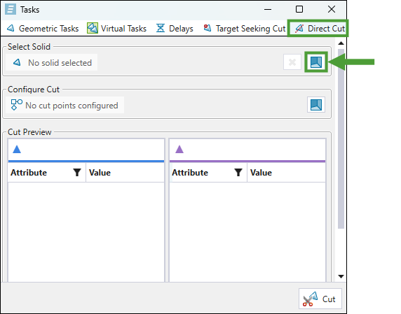
Note: Make sure you have the selection mode set to
 (Interactive Mode) and the selection type set to Object (see Using the Solid Model Viewer for more information).
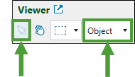
-
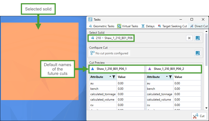
Click on the required solid in the viewer.
Evolution will automatically assign names to the tables in the Cut Preview section for the cuts that you will create in the next step. The names will be created by applying the default suffixes (_1 and _2) to the name of the solid that you selected (for example, Shaw_1_210_B01_P06_1 and Shaw_1_210_B01_P06_2, as shown below).
Note: The attributes featured in the tables correspond to the attributes of your model. The attribute values will be calculated when you perform the cut.
Note: To calculate the new attribute values, Evolution uses the aggregation methods and parcelling rules that you have defined when importing your dynamic solids model. If you have set any user-defined values during import, the default parcelling behaviour will be based on them. See Importing a Dynamic Solids Pit, Parcel Reporting in dynamic solids setups, and User-Defined Targets for more information.
Tip: To rename a cut, double-click the cut name in the Cut Preview table and enter the new name.
-
Perform the cut.
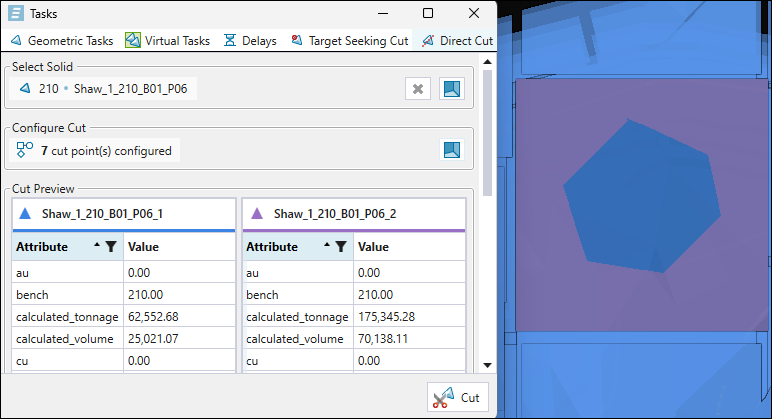
Click
(Configure cut points in the 3D viewer) in the Configure Cut section. Next, left-click on the selected solid to place the cut points and finish by right-clicking to confirm your selection. The resulting solid cuts will be differentiated with blue and violet colours, corresponding to the column colours in the Cut Preview table.
Note: To ensure precise solid selection during cutting operations, the view is automatically switched to plan view. Camera controls are limited to translation and zoom; rotation is disabled.
Note: You can assign from 2 to 20 points to define a cut line.
Tip: You can also define cut shapes as cut-out areas, instead of projecting straight lines to the solid's perimeter.
Tip: Click on the Attribute column in the Cut Preview section to sort the attributes in alphabetical order (ascending or descending).
Tip: Click the
 button in the Attribute column to display only the required solid attributes. You can also apply advanced filters to display only the required values.
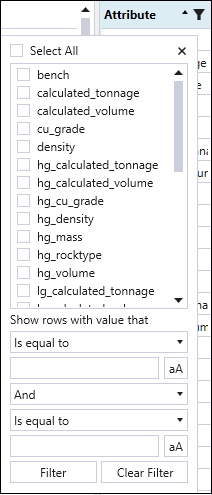
-
Click the
Cut button at the bottom of the Tasks panel.
The solid split will be reflected in the viewer.
See Common features for information and tips on viewing and managing split solids.
Target Seeking Cut
The target-seeking cut feature in Epoch automatically determines cut locations based on set target quantities. This solid cutting method allows you to achieve the following:
-
Define accumulation targets for each period of your setup.
-
Automatically create tasks when you specify the equipment.
Note: Target-seeking cuts allow you to create sequences for each digger shift-by-shift.
-
Guided cutting based on your quantity requirements.
Performing target-seeking cuts
Follow these steps to perform target-seeking cuts in your dynamic solids model:
-
Enter the
Target Seeking Cut tab of the Tasks panel.
See Accessing solid cutting feature for details.
-
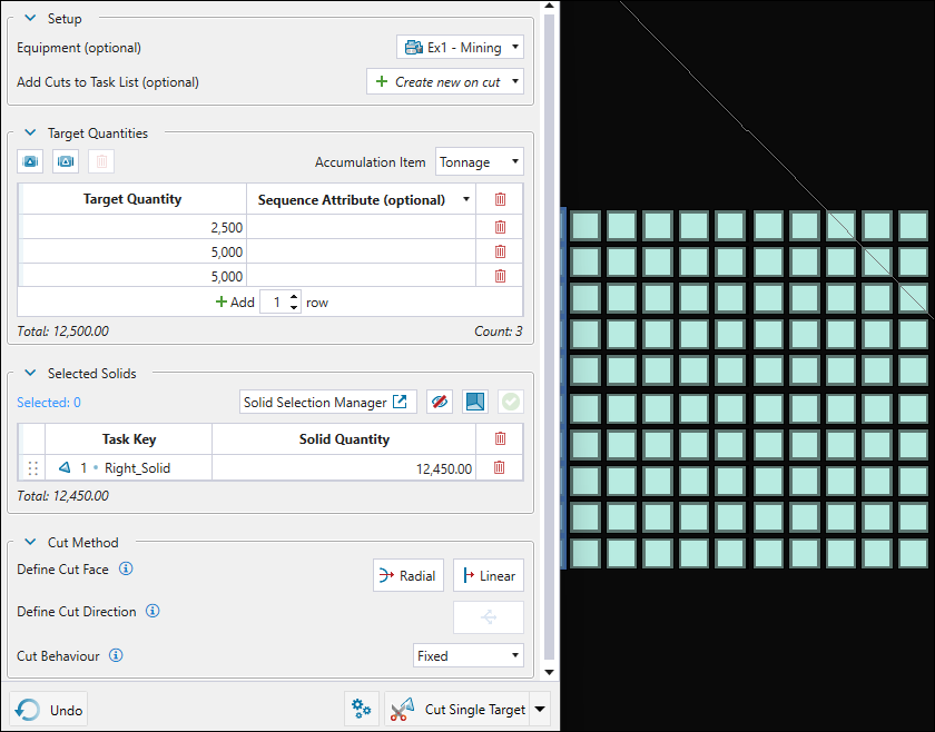
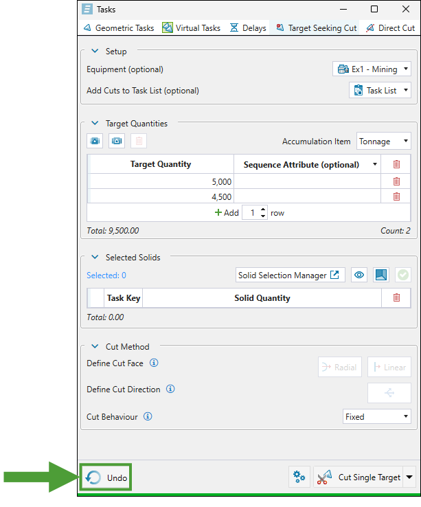
Configure the following sections:
-
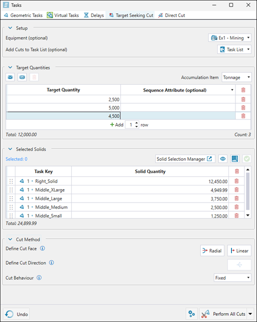
Setup. Set the following components as needed:
-
Equipment (optional). Select the digger equipment for which you want to create the task sequence.
Note: The cut_digger attribute is automatically created and a default value of 0 is set inside all solids when you are importing a new dynamic solids model. You can assign it to the task keys attributes in the
 Task Keys subtab (see Task Keys for more information).
Note: The Equipment drop-down will list all diggers for which you have assigned an activity in the
 Activity Sequence subtab (see Activity Sequence for more information).
 -
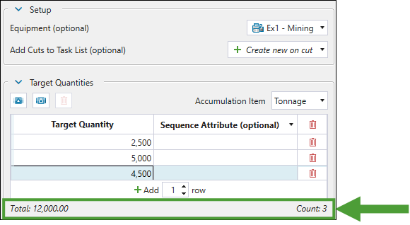
Add Cuts to Task List (Optional). Choose an existing task list or select
 Create new on cut to allow Evolution to create a new task list automatically based on your target-seeking cut configuration. For more information on task lists in Epoch, see Task Lists.
-
-
Target Quantities. Configure the following:
-
Accumulation Item. Using the drop-down, select the accumulation type for your target.
Note: The accumulation types listed in the drop-down correspond to the attributes you have configured for your setup. These accumulation types will be also listed in the
 Parcel Reporting subtab. See Parcel Reporting in dynamic solids setups for more information.
 -
Target Quantities. Set the target quantities using one of the following methods:
-
 (Populate from accumulation). Import the target values based on the equipment's raw material movement capacity multiplied by the number of periods. You can set this value in the
  Resource Productivity subtab when you have the Accumulation mode set for your Epoch setup (see Resource Productivity in Accumulation mode for more information). This will provide theoretical maximum targets for the selected equipment.
 -
 (Populate from effective accumulation). Import the target values based on the capacity adjusted for equipment availability and utilisation. This will provide more realistic targets that account for operational constraints.
Example: If you have the Combined Utilisation for a digger set to
1(100%) in Period 1 and to0.8(80%) in Period 2 in the Resource Definitions tab, and the Accumulation for both these periods set to
 50000in theResource Productivity subtab, the imported target quantities for that digger will be equal to 50000 and 40000.
See Resource Definitions and Resource Productivity in Accumulation mode for more information. -
Enter target quantities manually. Click
 <enter the required number> row(s) to enter the required number of rows for the target values.
Tip: Click on the row to change the assigned target value. To remove a row from the table, click the
 button.
Evolution will display the total tonnage and count below the target list.
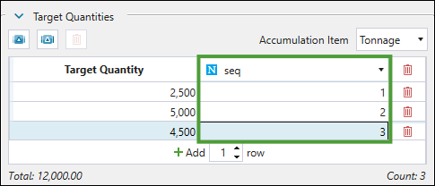
 Note
Note
The drop-down in the Sequence Attribute (optional) column contains solid-level attributes that are shared across all pits in the setup, excluding the following attributes:Attributes used for the task keys
Attributes set to the pit's bench, density or region
ID
SolidX
SolidY
SolidZ
calculated_tonnage
calculated_volume
cut_number
cut_digger
When you select the required attribute from the drop-down, you can assign a value in the cells below the header (number or text, depending on whether the attribute you chose was a numeric or text attribute). These values will then be assigned to the resultant solid's attribute. If you choose a numeric attribute, assign a value in the first row and then add more rows to the table, Evolution will assign an incremented value to each consecutive row.
To add solid-level attributes, see Maths Scripts for Solid Models.
-
-
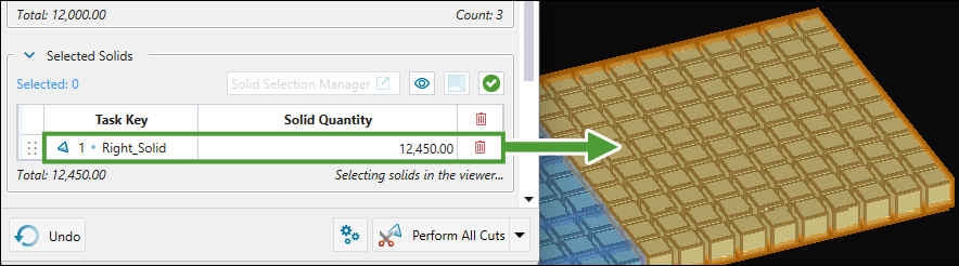
Selected Solids. Select the solids for which you want to perform solid cuts by doing one of the following:
-
Click the
 button in the Selected Solids section and select the required solids in the viewer. Evolution will provide the information on the total material quantity available from selected solids. Finish by clicking
  .
.
Or
-
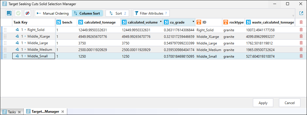
Click the Solid Selection Manager button to open up the Target Seeking Cuts Solid Selection Manager tab in the Tasks panel.
Note: If you have previously selected any solids to be cut, the tab will also include them.
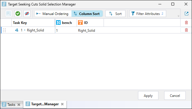
Note: The columns will default to the attributes that make up the task key. To add more attributes, click the
 Filter Attributes button. See Target Seeking Cuts Solid Selection Manager below for details.
To select the required solids, click the
button at the top of the tab and select the solids in the viewer. Finish by clicking .Tip: Toggle the
 (Show all selected solids) button to display all solids you have added to your selection.
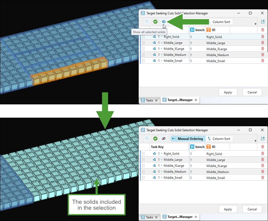
Alternatively, hover over a row in the table to check which solid corresponds to it in the viewer (this feature is enabled when you do not toggle the (Show all selected solids) button on).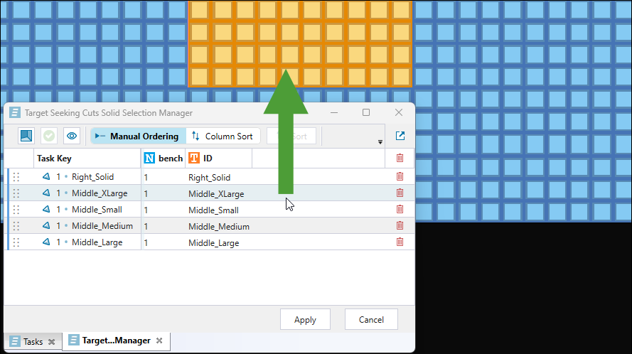
Note: To remove a solid from your selection, click the
button corresponding to the solid in the table. You can also select multiple solids while holding Ctrl, then press Delete to remove them all at once. Click for more information on the Target Seeking Cuts Solid Selection Manager tab
The Target Seeking Cuts Solid Selection Manager tab allows you to sort the selected solids, thereby specifying the sequence in which they will be cut, as follows:
-
To include more solid attributes in your view, click the
Filter Attributes button. Next, in the Attribute Filter panel, drag the required attributes to the Displayed Attributes column. Similarly, to remove the attributes you no longer need from your view, drag them back to the Hidden Attributes column. Confirm by clicking Save.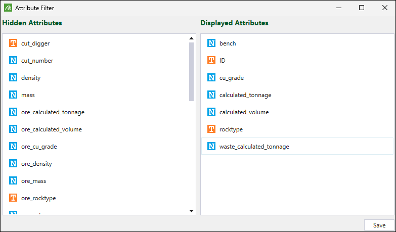
-
Choose how you want the solids to be sorted by clicking either the
 Manual Sorting or
  Column Sort button.
-
For
Manual Sorting, drag the solids to order them within the list as required. -
For the
Column Sort option, sort the solids as follows:-
Click on the attribute column header to order the solids based on the given attribute, in the ascending or descending order.
Or
-
Click the
Sort button, add the required attributes to the list by clicking New Sort and selecting them from the drop-downs, and specify whether they should be sorted in Ascending or Descending order.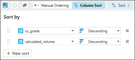
Note: Dragging is disabled in this mode.
Tip: You can additionally sort the solids based on multiple attribute columns. To do so, click
 corresponding to the attribute that you want to reorder and drag it to the required position on the list. The order of the attributes in the Sort By menu will determine the attribute's priority when sorting the solids.
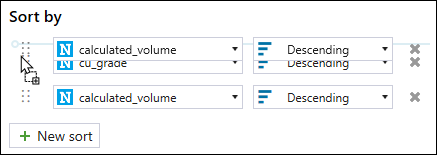
-
After finishing ordering the solids, click Apply to save your changes.
Evolution will close the Target Seeking Cuts Solid Selection Manager tab and reflect your settings in the Tasks panel.
-
-
-
Toggle the
(Show all selected solids) button in the Selected Solids section to display all solids you have added to your selection. 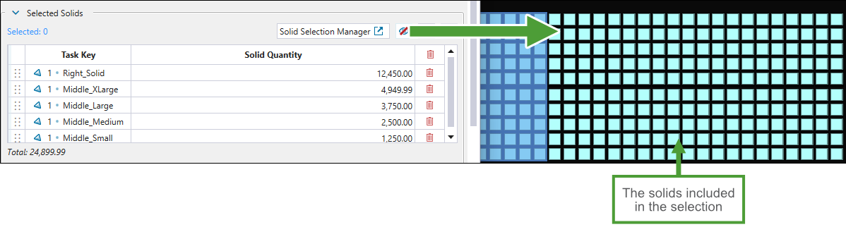
-
Hover over a row in the table to check which solid corresponds to it in the viewer.
-
Click the Task Key column header to sort the column alphabetically. Click it again to sort in reverse alphabetical order.
-
Reorder the listed tasks by clicking
corresponding to the task that you want to reorder and dragging it to the required position on the list. 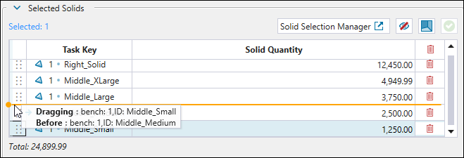
-
-
Cut Method.
Tip
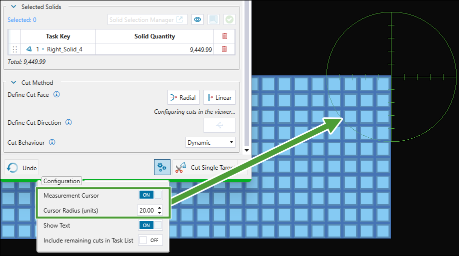
Click
 (Configure Viewer Visuals) at the bottom of the Tasks panel to customise the viewing options while specifying the required cut method and to manage task lists in relation to the remaining solids, as follows:
 -
Click the Measurement Cursor toggle button to apply the distance scale in the viewer while specifying the linear cuts. You can also set the cursor radius by entering the required value in the corresponding field (the units will follow the settings that you have applied in your project).
-
Toggle the Show Text button to show or hide the radius length information when defining radial cuts.
-
Enable the Include remaining cuts in Task List toggle button to add the remaining solids to the task list when performing cuts.
Specify how solid cuts should be performed by setting the following:
-
Define Cut Face. Choose one of the following cutting methods:
-
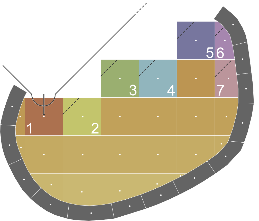
 Radial. Creates circular-shaped cuts that simulate the motion of a shovel swing during mining. To define the radial cut, click once in the viewer. The first click will define he pivot point and centroid of the cutting face.
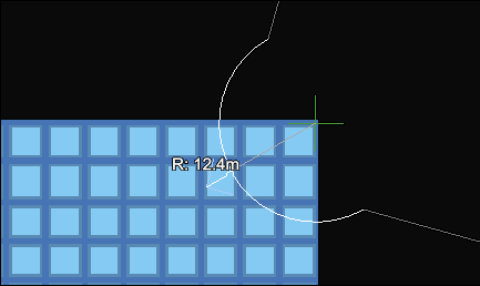
Next, place the arrow in the required direction and click again. This will indicate both the mining direction and the radius of the semicircle cut.
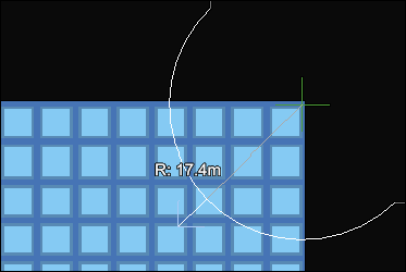
Tip: Press Ctrl while moving the cursor to snap the radius in increments of 10 units, based on the measurement settings defined for your project.
Or
-
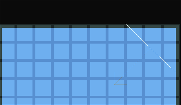
 Linear. Produces straight cuts based on the shape you draw.
To define linear cuts, you must left-click at least once in the viewer. If you right-click after the single left-click, Evolution will automatically apply the cut direction. If you left-click more than once and confirm with a right-click, Evolution will also prompt you to set the mining direction. To do that, set the required direction for the arrow in the viewer and left-click to confirm.
-
Hold Alt while hovering the mouse over the solid to fix the direction arrow in place.
-
Hold Shift to stagger the line as you hover the mouse over the solid. The line will change based on 22.5 degree increments.
-
-
-
Define Cut Direction. Click
 to edit the cut direction that you set while defining the cut face.
 -
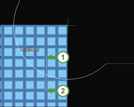
To define the cut direction for radial cuts, click to place the first point in the viewer, position the arrowhead as required and left-click to confirm.
-
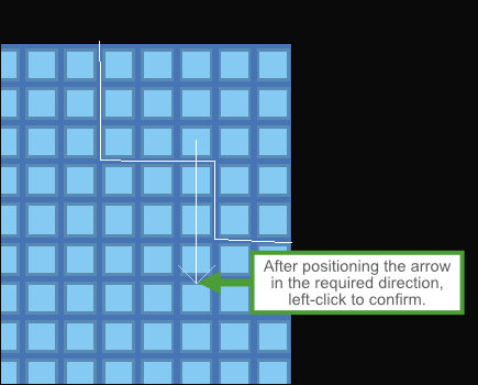
To define the cut direction for linear cuts, position the arrowhead as required and left-click to confirm.
-
-
Cut Behaviour. Using the drop-down, choose one of the following behaviours for cut orientation:
-
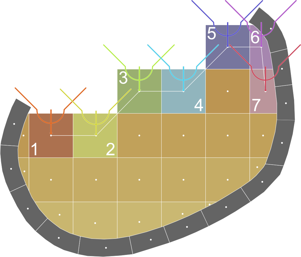
Fixed. Evolution will use the same cut face for the cuts (maintaining the original mining direction).
-
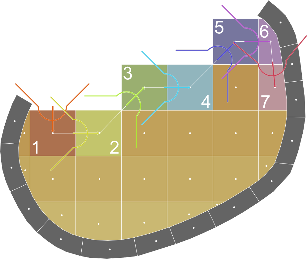
Repositioned. Evolution will move along the mining direction towards the solid centroid.
-
Dynamic. Evolution will orient the cut shape from previous solid centroid to current solid centroid (rotate the cut orientation based on centroid vectors).
-
-
-
-
-
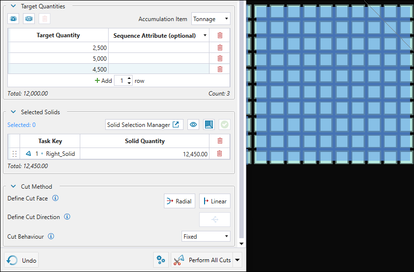
Perform the cut.
Choose whether to perform a single cut or all cuts at once by selecting the required option from the following drop-down:
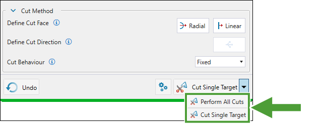
The different cut types allow you to achieve the following:
-
Single cut. Use the single cut approach if you are targeting a particular grade. Evolution will automatically calculate and take the required tonnage, so that you can inspect the resultant grade and then undo the cut if it doesn’t meet your targets. After that, you can adjust the cut configuration as required and redo it.
-
All cuts at once. Perform all cuts at once for the solids with insignificant material grade to meet your target per-period mass (volume).
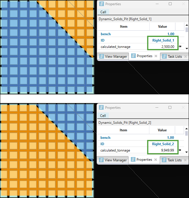
The table below compares the cutting behaviour when a single cut target and performing all cuts at once are set.
Note: All target-seeking cuts have a tolerance of 0.01.
-
|
|
Single cut (targeting 2500 tonnes) performed on solid Right_Solid (12,450.00 tonnes). The resulting solids (Right_Solid_1 and Right_Solid_2) have 2,500 tonnes
|
|
|
All three cuts (targeting 12,000.00 tonnes) performed on the selected solid (Right_Solid, 12,450.00 tonnes).
|
Simple Cut
The simple cut feature in Epoch allows you to perform simple solid cuts by specifying the target mass accumulation and the direction in which you want the mining to proceed. Evolution will slice through the selected solid in the predetermined mining direction and create solid cuts that meet the target mass.
Performing simple cuts
Follow these steps to perform simple solid cuts in your dynamic solids model:
-
Right-click on the required solid in the viewer and select
Simple Cut from the context menu. -
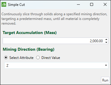
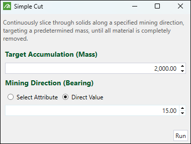
In the Simple Cut panel, specify the following:
-
Target Accumulation (Mass). Specify the target mass for each solid to be cut.
-
Mining Direction (Bearing). Specify the direction in which you want the mining to proceed by setting one of the following:
-
Select Attribute. Use the drop-down to select the attribute corresponding to the required mining direction.
-
Direct Value. Enter the angle measured in degrees clockwise from north (for example, a bearing of 90° points east, 180° points south, 270° points west, and 360° (or 0°) points north).
-
-
-
Click Run. Evolution will split the solid in the defined mining direction to create smaller solids that meet the target mass.
Example:
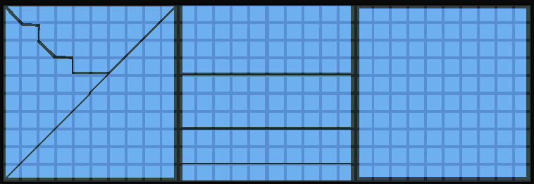
As shown in the example below, a simple cut targeting the mass of 2000 tonnes and proceeding in the Z direction was made on a solid with the total tonnage of 12,450.00 tonnes.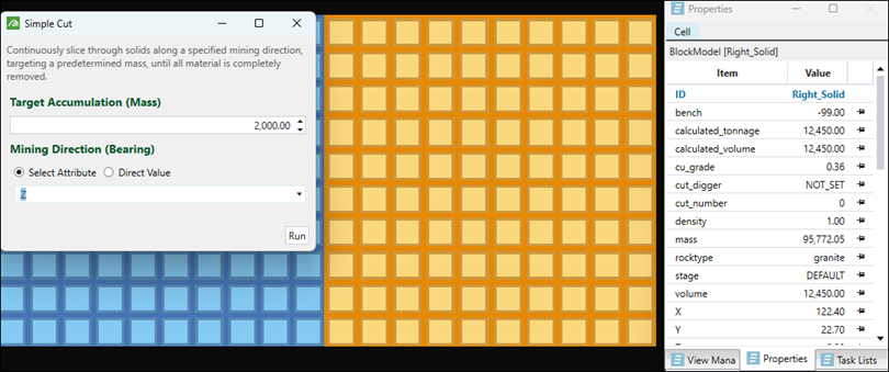
As a result, Evolution created six solids with the tonnage of 2000 and one solid with the tonnage of 449.99(as the tolerance of 0.01 was applied):
Integration with task lists
When you perform a solid cut, the parent solid is replaced with two child solids. Depending on the attributes that you have set for a task key, the existing tasks referencing solids may become invalid.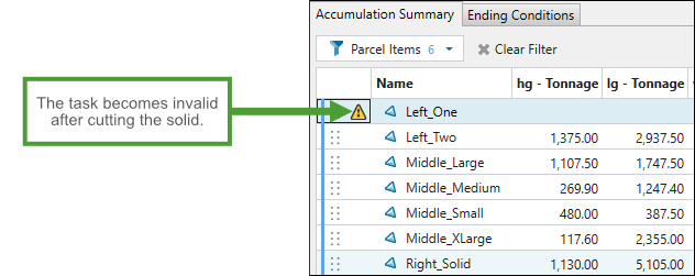
You can include the resulting solids into the task list by doing either of the following:
-
Add the task lists in the
 Task Sequence tab >
  Task Lists subtab.
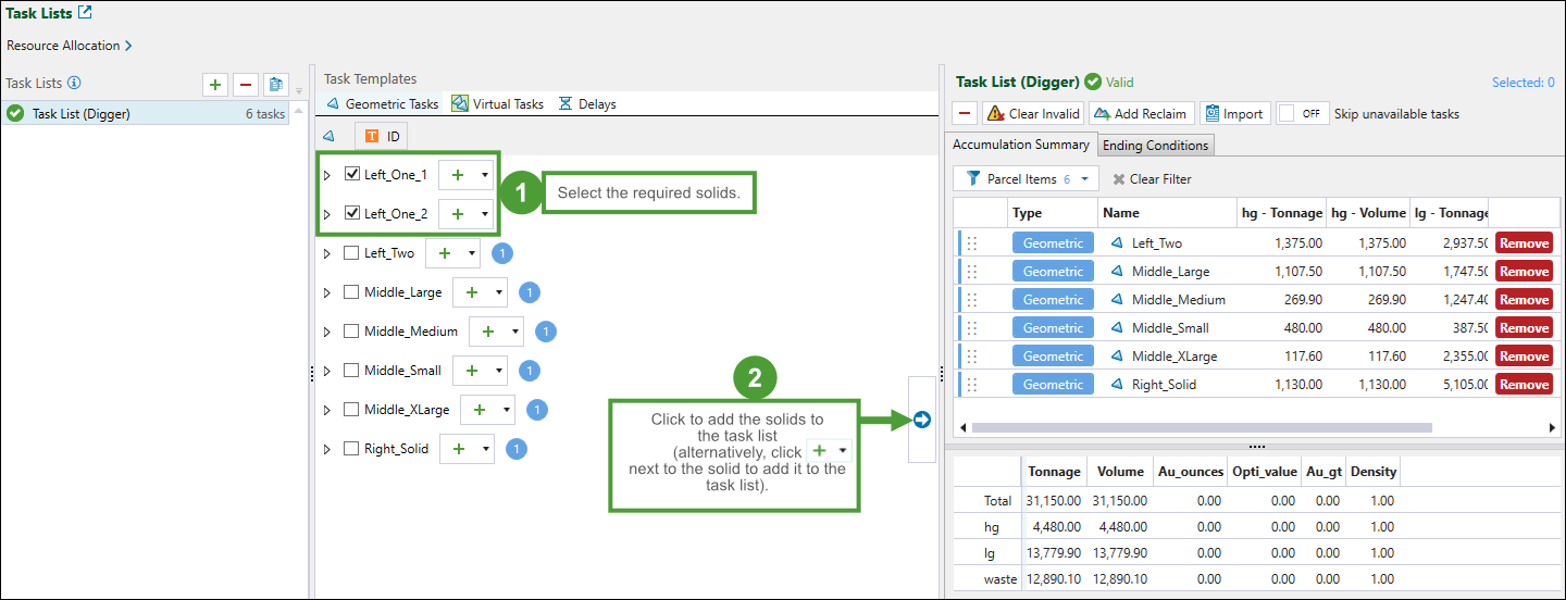
Tip: Tasks become invalid when no solids match their key attributes (for example, stage or bench). To delete all invalid tasks from the list, click the
 Clear Invalid button. To remove a single task (invalid or not longer needed) from the list, click the corresponding Remove button.
 -
Click
(Open Tasks window) in the Task Lists tab in the viewer and add task lists in the Tasks panel.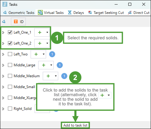
Tip: To delete all invalid tasks from the Task Lists tab in the viewer, click
(Remove all invalid tasks from task list). To remove a single task (invalid or not longer needed) from the list, click  (Remove tasks from task list).
 -
Press S while selecting solids in the viewer to automatically add them to your task list.
Important: Only digger equipment can be assigned to cutting tasks.
See also: Task Lists in the Task Sequence tab, Task Lists in Epoch viewer
Common features
The table below lists information and tips on common features that you can use while navigating through solid cuts.
| Improving solid visibility in the viewer |
|
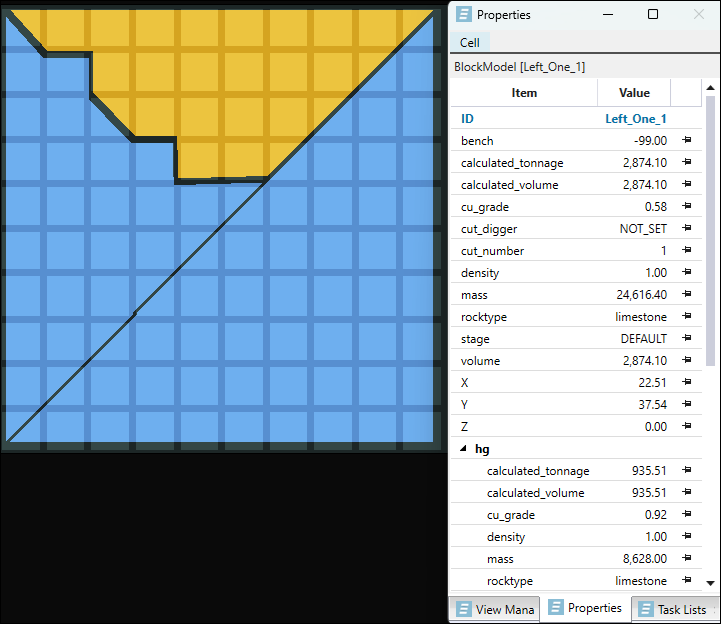
| Checking properties of a solid |
|
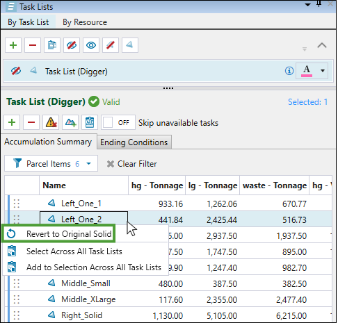
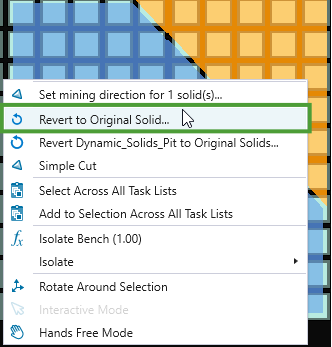
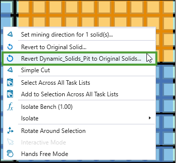
| Undoing solid cuts |
|
Importing and exporting solid cuts
The ![]() Export Cuts and
Export Cuts and ![]() Import Cuts tools enable you to save and load solid cut configurations within your models.
Import Cuts tools enable you to save and load solid cut configurations within your models.
These tools can facilitate working with solid cuts by allowing you to do the following:
-
Export solid cuts from a setup into a portable project model file.
-
Import previously exported cuts into a new setup or model.
-
Back up existing cuts before making changes to preserve prior configurations.
-
Track the progression of cuts across multiple scenarios.
Exporting solid cuts
Note: The export cuts option is only available if at least one model in the setup has been cut.
Follow these steps to export the solid cuts that you have applied in your models:
-
Enter the solid cuts export in one of the following ways:
-
Click
 Export Cuts in the toolbar at the bottom of the viewer.
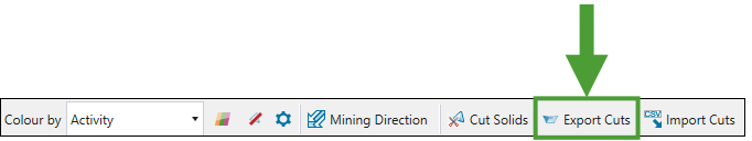
-
In the project explorer, right-click an Epoch setup where the required cuts were performed and select
Export Solid Cuts… from the context menu.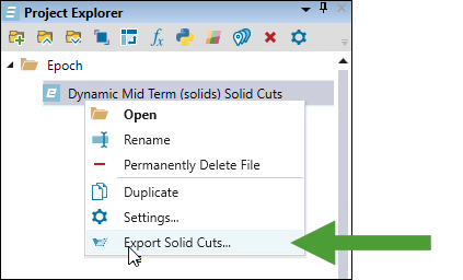
-
Right-click a solid model in the View Manager tab in the viewer and select
Export Solid Cuts… from the context menu.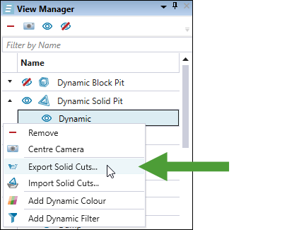
Note: You can also export solid cuts from multiple solid models. To do that, select them in the View Manager while pressing Ctrl and select the export option from the context menu.
The Export Cuts panel will appear.
-
-
Select the models from which you want to export solid cuts.
Optionally, edit the name for your export.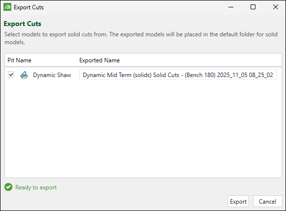
-
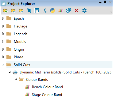
Click Export.
The solid model containing the applied solid cuts will be added to the project explorer.
Importing solid cuts
Before importing solid cuts, please note the following behaviour during the process:
All cuts existing in a model are removed from the setup.
Solids from the imported file replace the setup solids.
Solids are re-reserved against the block model(s), ensuring attribute values are recalculated with up-to-date data.
Tip: If you want to test new cut scenarios but preserve the old ones, proceed with exporting solid cuts first.
Follow these steps to import solid cuts into a model in your setup:
-
Enter the solid cuts import in one of the following ways:
-
Click
 Import Cuts in the toolbar at the bottom of the viewer.
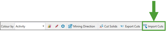
Or
-
Right-click a solid model in the View Manager tab in the viewer and select
 Import Solid Cuts… from the context menu.
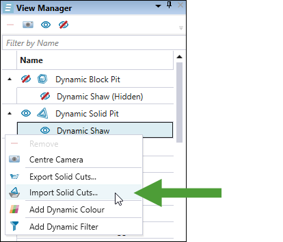
-
-
In the Import Cuts panel, select the models from which you want to import the solid cuts.
-
Using the drop-downs, select the attribute corresponding to the project solid ID properties in each selected model.
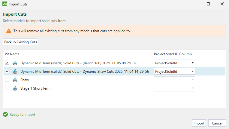
-
Click Import.
The pit models that are currently displayed in your viewer will be updated with the imported solid cuts.
