Creating CAD Objects
Below are some basic methods for drawing CAD objects to assist with modelling and analysing your projects.
See also: Getting Started > CAD and Modelling and tool groups under Menus and Tools > Create for detailed information on using CAD tools.
Create a line
Create a line in 3D space as follows:
-
Open some data in a view window.
-
On the Create ribbon tab, go to the Draw group. From the Line drop-down list, select
 Line.
Line.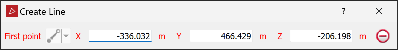
-
Pick the starting point in the view window. The X, Y and Z fields will populate. The cursor will snap to either of the following:
-
An object, if near one
-
The action plane, if in the empty space away from data
Note: When cross-hairs and a cyan square around the cursor appear, the cursor will snap to the action plane (see 1.1 The action plane on page 1). If only the cursor or an orange circle appears the cursor will snap to a point.
Tip: You can enter coordinates manually into the X, Y and Z fields and then press Enter to accept them. Press Tab to step between fields.
-
-
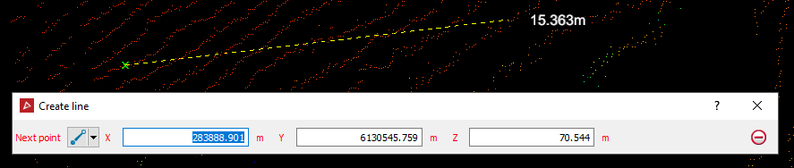
Pick, or press Enter at, the next vertex location. Repeat for all subsequent points.
-
Right-click to finish the line and save the change.
The line will be created as an object in the ![]()
cad container.
Tip: Press Esc at any time to clear the line and start over.
Create a polygon
To create a polygon follow these steps, using snap modes as needed:
-
Display scans to be modelled.
-
On the Create ribbon tab, go to the Draw group. From the Polygon drop-down list, select
 Polygon.
 -
Pick the First point for your polygon in the view window.
-
Continue clicking around the area of interest.
-
Click the right mouse button to complete the polygon.
-
Press Esc or click the
 button to
exit the tool.
button to
exit the tool.
The polygon will be created in the ![]()
cad container.
Tip: Create polygons while in top view or use the snap modes to make sure they are created in the intended location.
Create an offset line
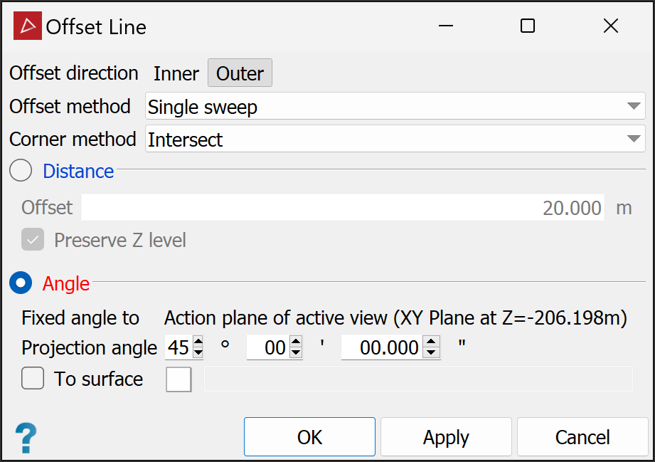
Follow these steps to project a line or polygon at a set angle to an action plane:
-
Set the action plane to the RL if projecting to the action plane. If projecting down to a surface place the action plane below the surface, and if up to a surface place the action plane above the surface.
Tip: To set the action plane as a horizontal plane at a set RL use the View > Action Plane > Set drop-down menu to select XY then select Move to point or hold down A and pick data at the desired RL.
-
Select and view the polygon or line to be offset.
-
On the Create ribbon tab, in the Create group, select
 Offset Line.
 -
Choose the Offset direction, as above.
-
Select the Angle radio button.
-
Enter the required Projection angle.
-
If projecting to a surface select the To surface checkbox and populate the field with the target surface.
-
Click OK or Apply.
The offset line or polygon will be saved in the

cadcontainer.
