Boundary
The Boundary group tools on the Query tab create horizontal polygons or edge networks at the elevation of the axes origin to depict the extremities of scans and surfaces.

|
|
Scan Extents (Ctrl+Alt+X) Create a polygon around the extents of a scan. |
|
|
Create edge networks to define boundaries of a surface. |
Scan Extents
The Scan Extents
tool (Ctrl+Alt+X) generates a polygon ![]() around a scan from the scan’s angular and range extents.
It also extracts the scan origin point and look direction of the
scanner.
around a scan from the scan’s angular and range extents.
It also extracts the scan origin point and look direction of the
scanner.
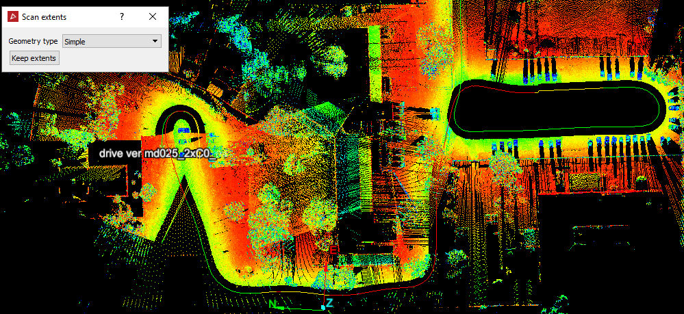
This tool also works with Maptek Drive scans. When a drive scan is selected and queried, the actual path followed by the driven vehicle will be displayed.
Create a scan extents polygon as follows:
-
On the Query tab, in the Boundary group, click
 Scan Extents.
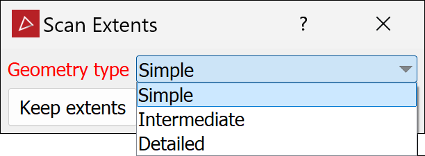
-
Select the type of polygon required from the Geometry type drop-down list, per below:
-
The Simple polygon is two connected arcs at the minimum and maximum range, extending between the horizontal angle limits.
-
The Intermediate polygon segments the horizontal angles into 15-degree increments and shows the minimum and maximum range in each segment.
-
The Detailed polygon is similar to the intermediate polygon except the angles are segmented in one-degree increments, to match the extents of the data more closely.
Note: Only Simple is available for drive scans.
-
-
Click Keep extents to save the extents as editable objects in the
cad container. These can be used to mask other
scan data to reduce overlap.
container. These can be used to mask other
scan data to reduce overlap.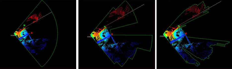
Examples of Scan extents: Simple (left), Intermediate (middle) and Detailed (right)
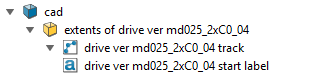
Note: For drive scans, the drive path
is saved in the cad ![]() container.
container.
|
|
|
A drive scan showing the vehicle path as the scan extents. |
Surface Boundaries
The Surface Boundaries
tool creates edge loops ![]() or edge networks
or edge networks ![]() that define the boundaries of a surface.
that define the boundaries of a surface.
Create a surface boundary as follows:
-
On the Query tab, in the Boundary group, click
 Surface Boundaries. Alternatively, on the
Create tab, in the Topography group, click Surface Boundaries.
Surface Boundaries. Alternatively, on the
Create tab, in the Topography group, click Surface Boundaries.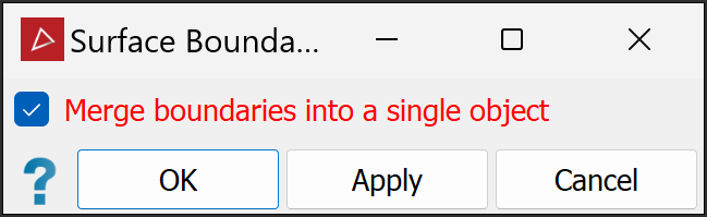
- Select or clear
Merge boundaries into a single object, as required:
Select to include all loops in a single edge network
 .
.Clear to create the edge loops as separate edge loops
 .
.
Or
-
Click OK or Apply to finish.
|
|
|
|
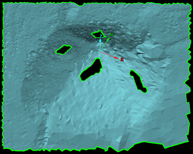
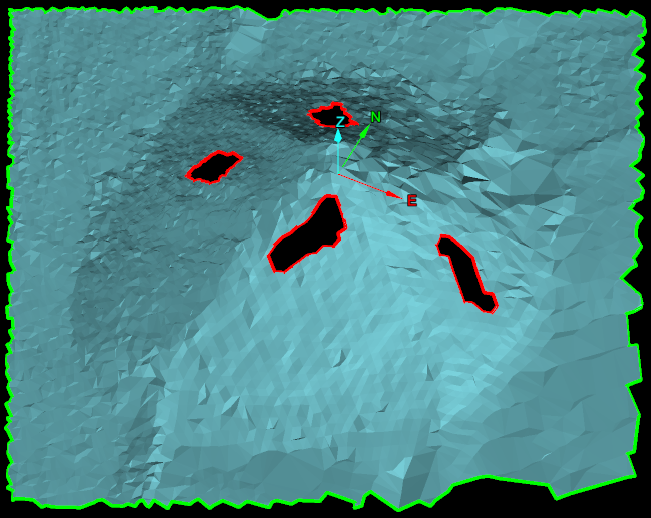
Surface boundaries have been created as a single edge network (left) and as edge loops (right). Edges are represented in green and holes in the surface are represented in red. |
|